IBEX TM67C Manual de usuario

ASSEMBLY GUIDE
TM67C Drum Mower

ASSEMBLY GUIDE
2022-01.0 IBEX EQUIPMENT CO. 1
Contents
Scope and Purpose .................................................................................................................................................. 3
Introduction............................................................................................................................................................. 3
Uncrating................................................................................................................................................................. 5
Drum support arm................................................................................................................................................... 6
Spring arm installation............................................................................................................................................ 6
Swivel pin ............................................................................................................................................................... 8
Blade installation .................................................................................................................................................... 9
Guard installation.................................................................................................................................................. 10
Spring arm attachment .......................................................................................................................................... 14
Safety Release (Breakaway Bar) .......................................................................................................................... 15
Transport lock ....................................................................................................................................................... 16
Drum unit pivot lock and restrictor plate.............................................................................................................. 16
Gearbox PTO Guards............................................................................................................................................ 17
Jack stand .............................................................................................................................................................. 19
Driveline installation............................................................................................................................................. 19
Lubrication........................................................................................................................................................ 20
Completion checklist ............................................................................................................................................ 21
Figure 1 assembled TM67C drum mower front view............................................................................................. 3
Figure 2 rear of mower showing pivot pin orientation ........................................................................................... 4
Figure 3 Drum Mower in crate as shipped.............................................................................................................. 4
Figure 4 parts removed from crate shown here for reference................................................................................. 5
Figure 5 Bags of small hardware shown sorted ...................................................................................................... 5
Figure 6 parts to connect arm to drum.................................................................................................................... 5
Figure 7 drum support arm before attachment........................................................................................................ 6
Figure 8 spring arm with blade change tool............................................................................................................ 6
Figure 9 long pin goes through as shown ............................................................................................................... 7
Figure 10 spring attachment hardware shown with springs.................................................................................... 7
Figure 11 springs attached at both ends but not in tension..................................................................................... 8
Figure 12 swivel pin................................................................................................................................................ 8
Figure 13 install pin with hole to back.................................................................................................................... 9
Figure 14 installing blades with the blade change tool........................................................................................... 9
Figure 15 guard holders ........................................................................................................................................ 10
Figure 16 set of 8 nuts and bolts used to attach guard holders ............................................................................. 10
Figure 17 guard holders shown installed on both ends of the drum unit.............................................................. 11
Figure 18 set of nuts and bolts are for guards and shield plates ........................................................................... 11

ASSEMBLY GUIDE
2022-01.0 IBEX EQUIPMENT CO. 2
Figure 19 guards hang from the guard holders and are secured with hardware shown........................................ 11
Figure 20 three shield plates install on top of the 2 large guards with curtains.................................................... 12
Figure 21 shield plates shown located on top of guards ....................................................................................... 12
Figure 22 PTO shields .......................................................................................................................................... 13
Figure 23 hardware to attach PTO guards ............................................................................................................ 13
Figure 24 shields installed as well as PTO guard ................................................................................................ 13
Figure 25 hang 3 point hitch and connect to mower............................................................................................. 14
Figure 26 pin to attach spring arm through top cap.............................................................................................. 15
Figure 27 top cap and spring arm bolted in place................................................................................................. 15
Figure 28 breakaway protection arm in mow position ......................................................................................... 15
Figure 29 hardware for spring arm transport lock ................................................................................................ 16
Figure 30 spring arm transport lock shown installed and in transport position.................................................... 16
Figure 31 hardware for pivot restrictor plate installation ..................................................................................... 17
Figure 32 pivot restrictor plate shown installed but loosened 2 turns for mow position...................................... 17
Figure 33 larger, oval-shaped guard is installed on the front of the gearbox, facing the tractor .......................... 18
Figure 34 smaller PTO guard installed on the 90 degree gearbox, facing the drum unit .................................... 18
Figure 35 lift the three point assembly up and install the jack stand.................................................................... 19
Figure 36 driveline identification and connection guide ...................................................................................... 19

ASSEMBLY GUIDE
2022-01.0 IBEX EQUIPMENT CO. 3
Scope and Purpose
This guide is limited to the Ibex TM67C (Galfre model 170) drum mowers sold by Tractor Tools Direct. The
guide covers models manufactured in 2013 and forward.
This manual is a guide to aid in the assembly of the drum mower models listed above. Consult the operations
manual for instructions on usage and safety.
Introduction
The photograph in Figure 1 shows a TM67C drum mower assembled completely from the front. Figure 2 shows
detail from the rear of the unit.
Figure 1 assembled TM67C drum mower front view

ASSEMBLY GUIDE
2022-01.0 IBEX EQUIPMENT CO. 4
Figure 2 rear of mower showing pivot pin orientation
Figure 3 Drum Mower in crate as shipped
The drum mower will arrive in a wooden crate disassembled for shipment. You will need a forklift or a front
loader with the proper lift straps to unload and move it safely.

ASSEMBLY GUIDE
2022-01.0 IBEX EQUIPMENT CO. 5
Figure 4 parts removed from crate shown here for reference
Uncrating
To make a good start of this project, unpack everything to be sure you are not missing anything and to check for
shipping damage. It makes finding what you need easier if everything is organized into like groups.
Figure 5 Bags of small hardware shown sorted
Take the 2 bags of small hardware and separate into like groups.
Figure 6 parts to connect arm to drum

ASSEMBLY GUIDE
2022-01.0 IBEX EQUIPMENT CO. 6
Drum support arm
The drum support arm is held in place with the long pin shown in the middle photo in Figure 6 above.
Figure 7 drum support arm before attachment
The arm shown in Figure 6 is shown here ready to install the long pin.
Spring arm installation
The spring arm holds 2 extension springs in tension to transfer some of the weight of the drum unit to the tractor
through the 3 point hitch.
Figure 8 spring arm with blade change tool

ASSEMBLY GUIDE
2022-01.0 IBEX EQUIPMENT CO. 7
Place the long pin with 2 holes through the lower set of holes on the support arm as shown.
Figure 9 long pin goes through as shown
Use the 2 links, washers, and cotter pin to attach the springs to the mower end as shown.
Figure 10 spring attachment hardware shown with springs
ASSEMBLY GUIDE
2022-01.0 IBEX EQUIPMENT CO. 8
Attach the springs to the 3 point end of the spring arm with the eye nuts, threaded rods, nuts, and washers as
shown. Do not tighten yet as it will make assembly difficult later.
Figure 11 springs attached at both ends but not in tension
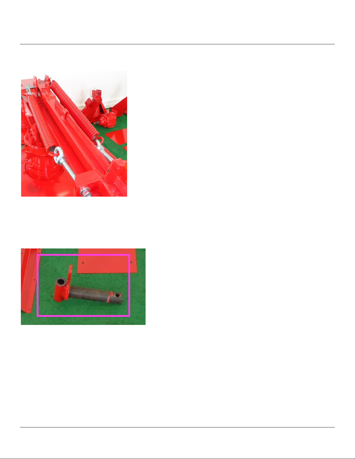
Swivel pin
Locate the swivel pin. This pin connects the three point hitch assembly and the support arm of the mower
together. The swivel pin allows the mower to swing back 90° for transport.
Figure 12 swivel pin

ASSEMBLY GUIDE
2022-01.0 IBEX EQUIPMENT CO. 9
Make sure the hole is to the back. Look at figure 2 to be certain you have it correctly oriented before
proceeding.
Figure 13 install pin with hole to back
Blade installation
Find the blades and separate them. Install them with the beveled edges face up.
Using the blade tool, pry open the drums and install the blade by fitting the hole of the blade over the pin inside.
Never put your hand or fingers inside the opened drum. The blade tool can slip off if it is raised too high.
Position the tool, raise the arm, install blade let the tool arm down. Be sure the blade is on the pin and swings
freely.
Figure 14 installing blades with the blade change tool
For correct balance, the blades should be replaced in sets. It’s always a good idea to keep at least one extra set
on hand during hay season.
Otros manuales para TM67C
1
Tabla de contenidos
Otros manuales de Cortacésped de IBEX


Manuales populares de Cortacésped de otras marcas


TALEN TOOLS
TALEN TOOLS AVR HGM30 Manual de usuario

DEWEZE
DEWEZE ATM-725 Manual de operación

Weed Eater
Weed Eater 180083 Manual de usuario

Husqvarna
Husqvarna Poulan Pro PP185A42 Manual de usuario

Better Outdoor Products
Better Outdoor Products Quick Series Manual de usuario

Cub Cadet
Cub Cadet 23HP Z-Force 60 Manual de funcionamiento


