Hunter BL Series Manual de usuario

BL Series Drum / Disc Lathe
7674-T, 09-22
© Copyright 2019-2022 Hunter Engineering Company
Page 1 of 30

1.1. Owner Information
BL Series Drum / Disc Lathe
Page 2 of 30

1.2. Getting Started
1.2.1. Introduction
This manual provides operaon instrucons and informaon required to operate the BL Series Drum/Disc
Lathe. This manual assumes that you are familiar with the basics of brake lathes. Secon 1 provides me-
chanical and electrical safety informaon as well as basic informaon about the BL Series Drum / Disc
Lathe. Following secons contain more detailed informaon about equipment, procedures, and maintenance.
Italicized references (for example, Refer to “Equipment Components” page 5.) are used to refer to specic
parts of this manual that provide addional informaon or explanaon. These references should be read for
addional informaon to the instrucons presented.
The owner of the BL Series brake lathe is solely responsible for arranging technical training. The lathe is to
be operated only by a qualied Hunter trained technician. Maintaining records of personnel trained is solely
the responsibility of the owner or management.
For further operaon instrucons for BL6x and BL7x lathes with ACT / Digi-Cal, refer to “Chapter 3. ACT /
Digi-Cal” of these instrucons.
1.2.2. For Your Safety
Hazard Definitions
Watch for these symbols:
CAUTION
Cauon: Hazards or unsafe pracces, which could result in minor personal injury or product
or property damage.
WARNING
Warning: Hazards or unsafe pracces, which could result in severe personal injury or death.
DANGER
Danger: Immediate hazards, which will result in severe personal injury or death.
These symbols idenfy situaons that could be detrimental to your safety and or cause equipment damage.
Important Safety Instructions
Read all instrucons.
All visitors and children should be kept a safe distance from the work area.
BL Series Drum / Disc Lathe
Page 3 of 30

To reduce the risk of re, do not operate the equipment in the vicinity of open containers of ammable
liquids (gasoline).
Do not let cord hang over edge of table, bench or counter, or come in contact with hot manifolds or moving
parts.
Do not operate the equipment with a damaged cord or if the equipment has been dropped or damaged -
unl it has been examined by a qualied service technician.
If an extension cord is necessary, a cord with a current rang equal to or more than that of the equipment
should be used. Cords rated for less current than the equipment may overheat. Care should be taken to
arrange the cord so that it will not be tripped over or pulled .
Always unplug equipment from electrical outlet when not in use. Never use the cord to pull the plug from
the outlet. Grasp plug and pull to disconnect.
Remove adjusng keys and wrenches. Form a habit of checking to see that keys and adjusng wrenches are
removed from tool before turning it on.
Keep the work area clean. Cluered oors, benches and areas around the lathe invite accidents
Do not use in a dangerous environment. Do not use in damp or wet locaons, or expose them to rain. Keep
the work area well lighted.
Wear proper apparel. Wear no loose clothing, gloves, neckes, rings, bracelets, or other jewelry which may
get caught in moving parts. Non-slip footwear is recommended. Wear protecve hair covering to contain
long hair.
Do not overreach. Keep proper foong and balance at all mes.
Always WEAR OSHA approved safety glasses. Everyday eyeglasses only have impact resistant lenses; they
are NOT safety glasses.
Also use face or dust mask if cung operaon is dusty.
Never stand on the tool. Serious injury could occur if the tool is pped or if the cung tool is unintenonally
contacted.
Keep guards in place and in working order.
Unplug tools before servicing, when changing accessories such as blades, bits,cuers, and the like.
Secure work. Use clamps or a vise to hold work when praccal. It is safer than using your hand and it frees
both hands to operate tool.
Do not force a tool. It will do the job beer and safer at the rate for which it was designed.
Use the right tool. Do not force a tool or aachment to do a job for which it was not designed.
Maintain tools with care. Keep tools sharp and clean for best and safest performance. Follow instrucons for
lubricang and changing accessories.
Use only Hunter recommended accessories. Consult the Brake Lathe Packages and Accessories Brochure
Form 3947-T for recommended accessories. The use of non-recommended accessories may cause risk of
injury to persons.
BL Series Drum / Disc Lathe
Page 4 of 30

Check for damaged parts. Before further use of the tool, a guard or other part that is damaged should be
carefully checked to determine that it will operate properly and perform its intended funcon - check for
alignment of moving parts, binding of moving parts, breakage of parts, mounng, and any other condions
that may aect its operaon. A guard or other part that is damaged should be properly repaired or replaced.
Never leave the tool running unaended. Turn the power “OFF.” Do not leave the tool unl it comes to a
complete stop.
Reduce the risk of unintenonal starng. Make sure switch is in “OFF” posion before plugging in.
SAVE THESE INSTRUCTIONS
1.2.3. Specific Safety Precautions / Power Source
Specications for Extension Cords
When using an extension cord, be sure to use one designed to carry the current your product will draw.
Make sure your extension cord is in good condion. An undersized cord will cause a drop in line voltage
resulng in loss of power and overheang. Table 1 shows the correct size to use depending on cord length
and name plate ampere rang. If in doubt, use the next heavier gauge. The smaller the gauge number, the
heavier the cord.
Power Source Grounding Instructions
In the event of a malfuncon or breakdown, grounding provides a path of least resistance for electric current
to reduce the risk of electric shock. This tool is equipped with an electric cord having an equipment-ground-
ing conductor and a grounding plug. The plug must be plugged into a matching outlet that is properly
installed and grounded in accordance with all local codes and ordinances.
Do not modify the plug provided - if it will not t the outlet, have the proper outlet installed by a qualied
electrician.
Improper connecon of the equipment-grounding conductor can result in a risk of electric shock. The
conductor with insulaon having an outer surface that is green with or without yellow stripes is the
equipment-grounding conductor. If repair or replacement of the electric cord or plug is necessary, do NOT
connect the equipment-grounding conductor to a live terminal.
Check with a qualied electrician or service personnel if the grounding instrucons are not completely
understood, or if in doubt as to whether the tool is properly grounded.
BL Series Drum / Disc Lathe
Page 5 of 30

Use only 3-wire extension cords that have 3-prong grounding plugs and 3-pole receptacles that accept the
tool’s plug.
Repair or replace damaged or worn cords immediately.
The Lathe is intended for use on all grounded supply circuits having a nominal rang less than 110VAC or
220VAC. An example of an 110VAC outlet on this type circuit is illustrated below.
The lathe has a grounding plug that looks like the plug illustrated above. Do NOT use adaptors that allow you
to bypass required equipment electrical grounding.
1.3. Operation Information
1.3.1. Equipment Components
Major Operang Controls
BL Series Drum / Disc Lathe
Page 6 of 30
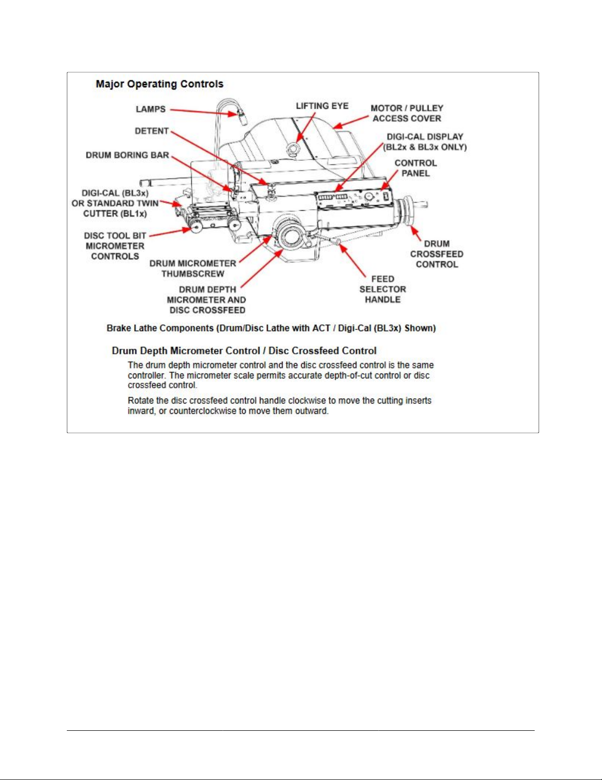
Disc Tool Bit Micrometer Controls
Disc tool bit micrometer controls are used to make accurate cung insert depth adjustments. Rotang
the controls clockwise feeds the cung inserts into the disc fricon surface, rotang the controls counter
clockwise moves them away from the disc surface
Drum Crossfeed Control
Rotate the drum crossfeed control handle clockwise, and the boring bar extends to move the cung insert
toward the inner edge of the drum diameter. Rotate the handle counter clockwise, and the insert moves
toward the outer edge of the drum diameter.
Feed Selector Handle
Select “DRUM” or “DISC” automac feed control with the feed selector handle
Control Panel
BL Series Drum / Disc Lathe
Page 7 of 30

“FEED RATE” dial is used to change feed rate from slow to fast. Slow is labeled as FINE. Fast is labeled as
COURSE. The recommended range of feed rates for One Cut Pass is also specied. One Cut operaon is
the method of cung a drum or disc in which, a single cut is used to remove fricon surface material and
provide the desired nish. This is a deep cut made at a slow feed rate.
“RETRACT DRUM BAR” indicator is a red LED that glows when the drum bar is NOT fully retracted in its
home posion.
“LIGHTS” buon turns the two LED work light ON and OFF.
“POWER” toggle switch turns the spindle motor and controls ON and OFF.
For the addional buons on the act / Digi-Cal control panel, refer to“Chapter 3. ACT / Digi-Cal” of these
instrucons
1.3.2. Drum and Disc Mounting
Typical Drum/Disc Mounting Congurations
These gures illustrate how typical hubbed and hubless drums and discs are mounted on the arbor. Adaptors
and / or collets t into the bearing seats or center holes as outlined below. Adaptors may be used as spacers
as needed. It is important that all surfaces contacted by adaptors are as clean as possible.
BL Series Drum / Disc Lathe
Page 8 of 30

Hubless Discs and Drums
Care should be taken to ensure the following:
All contact surfaces on the arbor, the centering cone, and the adaptors are clean.
Verify that the centering cone and the adaptors are free of nicks and burrs. If the contact surfaces are not
smooth, at, and making full contact, sand with ne emery cloth or replace.
BL Series Drum / Disc Lathe
Page 9 of 30

Verify that the arbor runout is no more than .0015 inch (.381 mm). The arbor should be cleaned prior to
installing. If the arbor is bent, replace with a new one.
Verify that the mounng surfaces on the disc are clean and free of any high spots. These high spots may be
eliminated by ling.
Proper mounng is important to ensure a correct nish.
Hubbed Discs and Drums
Care should be taken to ensure the following:
All contact surfaces on the arbor and split collets must be clean.
All grease, dirt and chips must be removed from grooves in split collets.
Verify that the arbor runout is no more than .0015 inch (.381 mm). The arbor should be cleaned prior to
installing. If the arbor is bent, replace with a new one.
All grease and dirt should be cleaned from the disc or drum hub prior to mounng.
Proper mounng is important to ensure a correct nish.
1.3.3. Spindle Speed Adjustment
Variable Speed Motor (Models BL6x or BL7x with ACT / Digi-Cal)
Pressing “SPEED” buon located in center of control panel toggles between high,medium and low speed,
indicated by the green LED switching to HIGH, MED or LOW.
Pressing “ACT” buon located in center of control panel will automacally vary speed, indicated by the green
LED. The ACT feature oscillates machining speed top prevent buildup of vibraon (chaer), requiring no
bands or other devices.
Belt / Pulley System (Models BL0x or BL1x)
1. Disconnect the power to the lathe.
2. Li the motor access cover to expose the motor and two pulleys
3. Release the belt tension by liing the handle on the motor base.
4. Move the ribbed belt to the desired set of pulleys, then release the handle on the motor base.
The recommended spindle speed is determined by measuring the diameter of the workpiece. The chart
below indicates the posion of the belt on the pulleys.
BL Series Drum / Disc Lathe
Page 10 of 30
Otros manuales para BL Series
1
Tabla de contenidos
Otros manuales de Torno de Hunter


