Hoval ServeCool Manual de usuario

System control for ServeCool
Operating Instructions
System control
for ServeCool
Operating Instructions
4 219 126-en-01

1 Use 3
1.1 Intended use .................................................................. 3
1.2 User groups ................................................................... 3
2 Basic principles 4
2.1 Operating modes ........................................................... 4
2.2 Setpoint sets.................................................................. 4
2.3 Operating and display elements on the control panel..... 5
2.4 Icons .............................................................................. 6
2.5 Buttons in the header..................................................... 6
3 Process diagram 7
3.1 Overview........................................................................ 8
3.2 Specications................................................................. 9
3.3 Fault messages.............................................................. 9
3.4 Process diagram.......................................................... 10
4 Data points 11
4.1 Night-time reduction..................................................... 12
4.2 Emergency operation................................................... 12
5 Zone control 13
5.1 Set points..................................................................... 14
5.2 Process diagram Zone................................................. 15
5.3 Data points Zone.......................................................... 16
6 Faults 17
2
System control for ServeCool
4 219 126-en-01
Content

1 Use
1.1 Intended use
The ServeCool system control is used for clearly laid-out operation of ServeCool
units. It is operated via the web application integrated in the controller with a
graphical user interface (Web GUI). Any web browser can be used for access via
the interface directly on the unit (recommended web browser: Google Chrome).
The system control gives trained users access to all information and settings that
are necessary for normal operation:
■Display and setting of operating modes
■Display of actual values (temperature, humidity, ow rate, ...)
■Display and setting of set values
■Display and programming of the annual calendar
■Display and handling of alarms and faults
■Display and setting of control parameters
■Password protection
Intended use also includes compliance with the operating instructions. Any usage
over and above this use is considered to be not as intended. The manufacturer
can accept no liability for damage resulting from improper use.
1.2 User groups
There are 4 user levels:
User level User group Access rights Access
Guest Untrained users ■Read rights
■Fault reset
free
LeveL 1 Trained users ■Read rights
■Write rights
– BMS set values
– Operating parameters
– Fault reset
– Control parameters
Protected by a password
Factory setting:
12345
LeveL 2 Trained users with
extended access
rights
■Read rights
■Write rights
– Calendar
– BMS set values
– Local set values
– Operating parameters
– Fault reset
– Control parameters
Protected by a password
(password handover at
commissioning of the plant)
LeveL 3 Super user ■Read rights
■Write rights
– Calendar
– BMS set values
– Local set values
– Operating parameters
– Fault reset
– Control parameters
Protected by a password
(password handover at
commissioning of the plant)
3
System control for ServeCool Use
4 219 126-en-01

2 Basic principles
2.1 Operating modes
The ServeCool unit has the following operating modes:
■Summer operation
■Winter operation
The system control controls and regulates the unit according to demand and
depending on the operating conditions. Switching between summer and winter
operation is carried out via the time program.
Operating
mode
Description Use
Summer
operation
The unit uses the following cooling processes depending on the
temperature and moisture conditions:
■Indirect free cooling with fresh air
■Indirect adiabatic cooling
■Mechanical aftercooling (for covering load peaks)
The chiller for supplying the cooling coil and the water supply are
in operation.
During the hot
season
Winter
operation
The unit uses the following cooling processes depending on the
temperature and moisture conditions:
■Indirect free cooling with fresh air
■Mechanical aftercooling (for covering load peaks)
The chiller for supplying the cooling coil is in operation. There is
no need for a water supply.
Attention
The adiabatic system must be drained and frost-proofed
during winter operation.
During the cold
season and
in transitional
periods
2.2 Setpoint sets
2 setpoint sets can be specied:
■Set values for local mode
■Setpoints for BMS operation
(The setpoints are specied by the building management system.)
4
System control for ServeCool Basic principles
4 219 126-en-01

2.3 Operating and display elements on the control panel
1
2
3
4
5
■
1
Operation indicator light
■
2
Indicator lamp and pushbutton Fault / Reset
■
3
Local / BMS selector switch
■
4
Network interface
■
5
Main switch
Operation indicator light
Green... ServeCool unit ON or in standby mode
O........ ServeCool unit OFF
Indicator lamp and pushbutton Fault / Reset
Red...... There is a fault message.
Press the button to acknowledge faults.
Local / BMS selector switch
■Local mode: The unit controller operates autonomously according to the
specications from the internal memory.
■BMS mode: The unit controller operates according to the specications from
the building management system.
Switching between local mode and BMS mode is done via the selector switch on
the control panel or via a software switch (software parameter 9000-08 in the Data
points screen). The following applies:
Setting
Control panel selector switch
Value
Software switch Valid
Local Local Local
Local BMS Local
BMS Local Local
BMS BMS BMS
Network interface
RJ45 interface for access to the unit controller
Main switch
The main switch disconnects the system from the power supply and, if necessary,
interrupts the optional UPS (uninterruptible power supply).
5
System control for ServeCool Basic principles
4 219 126-en-01

2.4 Icons
Icon Meaning
Edit value
Save value
Cancel
Display help text
Fault
Manual set value active
2.5 Buttons in the header
1 2
■
1
Open Process diagram screen
■
2
Open Data points screen
1 2 3
■
1
Fault exists |Show fault messages
■
2
Current user level |Enter password
■
3
Select language
6
System control for ServeCool Basic principles
4 219 126-en-01

3 Process diagram
The Process diagram screen shows the following information and buttons:
1
3 4
2
■
1
Overview: Information about valid set value specifications and the current operating mode
■
2
Process diagram with current measured values and status displays
■
3
Specifications: Entering the set values and the time program
■
4
Fault messages: Display and reset of faults
Notice
Depending on the installed unit type and optional components, the display
on the screen may dier from the display in this manual.
7
System control for ServeCool Process diagram
4 219 126-en-01
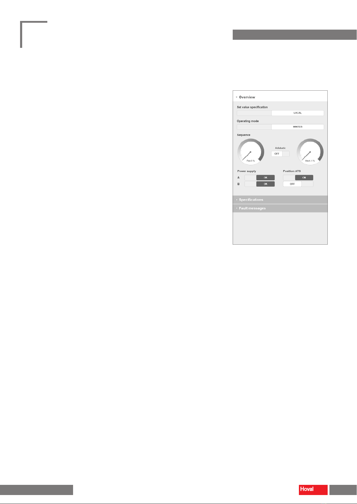
3.1 Overview
Set value specication
Display of the currently valid set value specication:
– Set values for building management system mode (BMS)
– Set values for local mode (Local)
Switching between local mode and BMS mode is done via the selector switch on
the control panel or via a software switch (software parameter 9000-08 in the Data
points screen).
Operating mode
Display of the current operating mode:
– Summer
– Winter
Switching between summer and winter operation is done via the time program
(see section chapter 3.2).®
Sequence
Display of currently used cooling processes:
– Indirect free cooling with fresh air
– Indirect adiabatic cooling
– Mechanical aftercooling
Power supply
Status display of the power supply
Position ATS (automatic transfer switch)
Display of currently used power supply
You can dene the priority for the power supply in the Data points screen
(control panel parameter 0000-06).
8
System control for ServeCool Process diagram
4 219 126-en-01
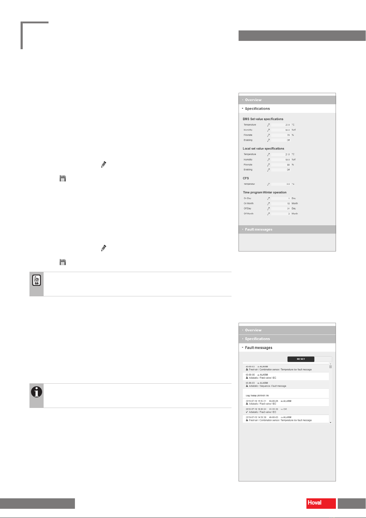
3.2 Specifications
BMS/Local set value specications
Displaying the set value specications for BMS operation, displaying and setting
the set value specications for local operation:
– Temperature (supply air)
– Humidity (supply air)
– Flowrate (supply air)
– Enabling (unit)
■In each case, click on the icon.
■Enter the desired value.
■Click the icon to save the value.
CPS
Dene the target temperature for the Condensation Prevention System to prevent
condensation of moisture in the recirculation air ow:
– Temperature (fresh air after admixture of exhaust air)
Time program Winter operation
Dene the period in which the unit runs in the 'Winter' operating mode.
■In each case, click on the icon.
■Enter the on and o dates for winter operation.
■Click the icon to save the value.
Attention
When switching to winter operation, ensure that the adiabatic system is
drained and frost-proofed.
3.3 Fault messages
The list of fault messages shows all faults with date and time of their occurrence:
– Active faults appear in red.
– Corrected faults appear in green.
■Click on 'Reset' to acknowledge faults.
Notice
The list of past faults is successively loaded by the unit controller.
For data that is further back in time, the loading times may be longer.
9
System control for ServeCool Process diagram
4 219 126-en-01

3.4 Process diagram
The process diagram shows a unit overview with current measured values and status displays.
10 Supply air
1003 Combination sensor supply air
1004 Bypass damper cooling coil
1005 Combination sensor E monitoring
1006 Supply air flowrate
20 Extract air
2000 Combination sensor extract air
2001 Extract air filter
30 Exhaust air
3003 CPS damper (Condensation Prevention System)
3004 Exhaust air flowrate
40 Fresh air
4000 Combination sensor fresh air
4001 Fresh air filter
4002 CPS damper (Condensation Prevention System)
50 Chilled water
5000 Cold water valve
60 Adiabatic
6000 Feed valve
6001 Drain valve
6002 Adiabatic pump
6003 Liquid level switch (too high)
6004 Liquid level switch (too low)
6005 Combination sensor conductivity measurement
6006 Flow sensor
70 Humidification
7000 Humidifier
7001 Hygrostat
7002 Drain valve
7003 Combination sensor humidifier
↑
Data point number: Under this number you will nd the component in the data point list.
10
System control for ServeCool Process diagram
4 219 126-en-01
Tabla de contenidos


