HOSCH HD-PU-L Manual de usuario

TYPE HD-PU-L
Installation and
Operation Manual
HOSCH
PRE-
SCRAPERS

©2016 HOSCH
Installation and Operation Manual Type HD-PU-LPage 2 of 14
The contents of this document may be subject to technical modifications
Important information
This manual is intended to help you install and operate this device safely and effectively. Read this
manual before installing and operating the device.
Pay particular attention to all warnings and cautions throughout this manual. If you do not obey all the
warnings and procedures in this manual, it can lead to serious damage to property and/or cause
injury to personnel. If there is any safety instruction or procedure that you do not understand, do not
use the device. Contact your supervisor or the relevant safety manager.
This device has to be installed and operated only for its intended use to prevent damage and injuries.
All required actions have to be carried out by people who have been properly trained.
It is the user's responsibility to make sure that the device is only used in full accordance with the rules
and regulations of the relevant site.
The following conditions are required:
1. Competent configuration of the device for intended use only
2. Installation of the device according to this installation and operation manual
3. Operation of the device under the following operating conditions
4. Periodic maintenance according to these instructions
Optional operating conditions
If the device is to be installed in different operating conditions than those specified above, consultation
with HOSCH is required. The operation of the device outside the above stated operating conditions
can lead to serious damage to property and/or to possible injury.
Do not use the device in its standard version in explosive environments (ATEX). For special versions
please contact HOSCH.
SAFETY
600 mm to 2,400 mmBelt width
Up to 5.5 m/s; up to 2.5 m/s with mechanical belt splices.Belt speed
Rubber or PVC, with a flat surface,
hardness recommended > 60 Shore-A
Belt type
Vulcanized belt joints. The cover hardness of the spliced area should not
deviate more than 5 Shore-A from the undisturbed section.
Mechanical splices.
Belt splice
-20 °C to +80 °CAmbient temperature
Uni and bi-directionalDirection of belt travel
Intended use
Use
The HOSCH pre-scraper Type HD-PU-L is installed at the discharge pulley of the conveyor belt
system, reducing the material layer sticking to the belt. Consequently, the following main scraper can
operate under more favourable conditions, resulting in optimal overall cleaning results.
General operating conditions
Item Conditions

©2016 HOSCH
Installation and Operation Manual Type HD-PU-LPage 3 of 14
The contents of this document may be subject to technical modifications
Modifications to Parts
Do not attempt to make any modifications or alterations to the device regarding the configuration,
installation, operation and maintenance without written approval from HOSCH. Unauthorised modifi-
cations or alterations to the device could lead to serious damage to property and personnel.
General Danger Notice
During operation, unexpected deflection movements may occur. Danger of entrapment exists. The site
operator should guard the mountings (railings, danger signs, etc).
The wearing of scraper parts may cause sharp edges. The risk of injury during installation or
maintenance exists.
Prevent the scraper from unintentional pivoting.
Due to the friction that occurs during operation, the blades or module tips are likely to become very
hot. Touching them immediately upon stopping the belt can lead to serious burns.
The contact between the blades or modules and the running conveyor belt can create static electricity.
Be cautious when touching the device! Attention: Sparking may occur through discharge.
Mineral or metallic particles may collect on the belt surface and, in exceptional cases, cause sparking
when passing the blades or modules.
The weakened structures of worn parts are likely to break. To guarantee personal and conveyor safety,
these parts have to be replaced with new ones.
Safety precautions during installation and maintenance work
Carry out installation or maintenance work on the scrapers only after the conveyor belt has been
stopped and "locked-out". The working area has to be isolated. Do not begin any work that has not
been previously authorised by a responsible person.
Protective clothing, in particular safety boots, gloves, helmet and protective glasses are mandatory.
An authorised work permit from the relevant manager must be obtained prior to any welding and
cutting work.
When working at heights, provide safety devices, for example scaffolds, railings, guard nets, safety
harnesses. The devices must have been inspected and released as fit for work.
Prior to operating the scraper, ensure that the site is completely cleared. All equipment or parts, such
as scaffolds, lifting gears, tools etc. should be removed from the area prior to restarting the conveyor
belt. Safety devices (hoods, guards etc.) that may have been dismantled must be refitted.
All screwed connections are to be checked and secured before each stage of commissioning and after
each service. Security components (spring washers, counter nuts) should not be re-used. They must be
replaced with new parts. In case of mechanical damage, e.g. corrosion, new parts must be installed.
Only original, genuine HOSCH parts should be used.
SAFETY (Continued)

©2016 HOSCH
DBFAE
A
B
D
E
F
CBDAC
A
B
C
DD
Installation and Operation Manual Type HD-PU-LPage 4 of 14
DESCRIPTION
Main items – Belt width 600 - 1,050 mm
Cleaning block
Assembly carrier
Mounting with tensioning unit
Mounting
Clamp ring
The contents of this document may be subject to technical modifications
Main items – Belt width 1,200 - 2,400 mm
Cleaning block
Assembly carrier midsection
Assembly carrier end section
Mounting with tensioning unit

©2016 HOSCH
Installation and Operation Manual Type HD-PU-LPage 5 of 14
The contents of this document may be subject to technical modifications
DESCRIPTION (Continued)
Design
The HOSCH pre-scraper Type HD-PU-L is known as a head-pulley scraper. The characteristics of the scraper
are the single-row PU cleaning blocks. For belt widths up to 1,050mm, the assembly carrier is of a one-piece
design and is fitted with one single tensioning unit. For belt widths of more than 1,050mm, the scraper is
equipped with 2 tensioning units and the assembly carrier is divided into 3 parts.
Function
The centerpieces of the scraper are its cleaning blocks (A) made of highly abrasion-resistant PU material. During
operation, the cleaning blocks are kept in contact with the belt surface by the tensioning unit (D).
The assembly carrier is fixed within the mountings (D, E (up to1,050 mm)) and is turnable. These mountings are
bolted to the belt conveyor frame and the distance between them should be kept to a minimum to provide maxi-
mum support.
List of tools
For the scraper installation and maintenance the following tools are required as a minimum:
• 2 of ring/open-end spanner 19 mm
• 2 of ring/open-end spanner 24 mm
• 1 of assembly lever
• 1 of measuring tape 2 m
• 1 of fitter's square 160x250
• 1 of hand-brush
• 1 of wire brush
• 1 of one-hand right-angle grinder
• 1 of marker pen

©2016 HOSCH
øA
R
E
0-30°
C
D
PC
100
160
80
70
15
40
65
∅14
PC
105
95
400 – 750
800 – 1250
Cmin:225 mm
D: 222 mm
Installation and Operation Manual Type HD-PU-L
Page 6 of 14
INSTALLATION
The contents of this document may be subject to technical modifications
1. Determine the installation position
1. Find out the radius “R“.
2. Add the radius “R“ to the measurement “E“ (see illustra-
tion) and draw an arc of a circle with this measurement
around the pulley centre point.
3. Find out the assembly carrier centre point “PC“. With the
measurement “C”, draw a line horizontal to the centre
line of the pulley.
At “Cmin“, the tip of the cleaning block is located at
the “3 o’clock position”. HOSCH recommends
selecting “C” in such a way that the cleaning tip is
located between 0° (3 o’clock) and 30° (4 o’clock).
Pulley diameter øA [mm]
2. Determine the position of the mountings
1. Determine the position of the mountings from the assem-
bly carrier centre point “PC”.
2. The mountings should preferably be installed at solid
unbendable conveyor frame parts, e.g. beams.
Dimension E[mm]

©2016 HOSCH
60
290
60
120
PC
Installation and Operation Manual Type HD-PU-LPage 7 of 14
The contents of this document may be subject to technical modifications
INSTALLATION (Continued)
3. Cut out the installation hatch
1. Measure and mark the installation hatch relative to the
point “PC“.
2. Cut out the hatch.
Tip: The dimensions of the installation hatch are the
minimum required to allow the assembly carrier with
the installed cleaning blocks to slip through the hatch.
4a. Install the mounting (belt width 600 - 1,050 mm)
Install the mounting on one side.
For belt widths up to 1,050mm, install only one mounting
in the first step.

©2016 HOSCH
3
2
1
5. Install the cleaning blocks
Fix the cleaning blocks (1) to the assembly carrier (3)
with the set of bolts (2).
4b. Install the mountings (belt width 1,200 - 2,400 mm)
Install the mountings on both sides.
For belt widths of 1,200 up to 2,400 mm, install one
mounting with tensioning unit on each side.
Installation and Operation Manual Type HD-PU-LPage 8 of 14
The contents of this document may be subject to technical modifications
INSTALLATION (Continued)

©2016 HOSCH
2 1 2
3 2
6a. Install the assembly carrier (belt width 600 - 1,050 mm)
1. Slide the assembly carrier through the installation
hatches.
2. Slide the assembly carrier tube into the installed mount-
ing.
3. Push the second mounting (tensioning side) over the
assembly carrier and bolt it to the conveyor frame.
6b. Install the assembly carrier (belt width 1,200 - 2,400 mm)
1. Introduce the assembly carrier midsection (1) into the
chute.
2. Slide the assembly carrier end-sections (2) through the
mountings and insert them fully into the carrier midsec-
tion. Ensure that the pins welded inside the midsection
align with the notches on the end sections.
3. Tighten the clamp screws (3).
Note: Alternatively, if there is enough space avail-
able, you may slide the assembly carrier into the
chute from outside directly after completing installa-
tion steps 4a and 6a.
Installation and Operation Manual Type HD-PU-LPage 9 of 14
The contents of this document may be subject to technical modifications
INSTALLATION (Continued)
©2016 HOSCH
==
1
2
1
Installation and Operation Manual Type HD-PU-LPage 10 of 14
The contents of this document may be subject to technical modifications
INSTALLATION (Continued)
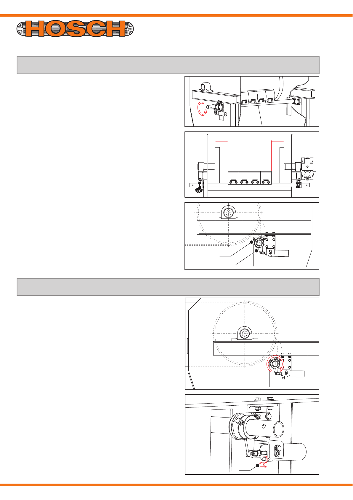
7. Centre the assembly carrier
1. Turn the assembly carrier until the cleaning blocks
contact the belt surface.
2. Centre the assembly carrier.
3. Tighten the clamp bolts (1) on the tension lever (2).
8. Pre-tension the assembly carrier
1. Turn the assembly carrier slightly backwards against the
spring tension.
2. Turn the tension lock (1) down.
3. The tensioning unit is now active and presses the clean-
ing blocks against the belt.
Tabla de contenidos
Otros manuales de Herramientas eléctricas de HOSCH


