Honeywell 8712009 Instrucciones de funcionamiento originales

Page 1
Models 8712009, 8712109, 8712309, 8712409
Read this manual carefully before installing and operating!
ENGLISH
Installation & Operation Guide
Digital Deadbolt

Page 2
Index
INSTALLATION INSTRUCTIONS
Package Contents / Tools Required.............................................................Page 1
Prepare Door and Jamb.................................................................................Page 2
Adjusting Deadbolt Latch Set.......................................................................Page 3
Installing Deadbolt Latch Set........................................................................Page 4
Preparing Interior Assembly.........................................................................Page 5
Installing Exterior Assembly..........................................................................Page 6
Installing Interior Assembly...........................................................................Page 7-8
OPERATION INSTRUCTIONS
Exterior Assembly Overview.........................................................................Page 9
Locking and Unlocking / Changing Programming Code /
Adding User Codes........................................................................................Page 10
Deleting User Codes / Automatic Lock Function /
Temporarily Disable Auto Lock...............................................,,,,,,,,,,,,,.........Page 11
Vacation Mode / Secure Lock-out Period / Sound ON and Off
Restore Factory Settings / Low Battery Warning.......................................Page 12
Consumer Friendly Message Guide / Programming Record...................Page 13
Installation Trouble Shooting........................................................................Page 14
Template.........................................................................................................Page 15-16
Consumer Assistance...................................................................................Page 17
Limited Warranty...................................................................................Back Cover

Page 1
INSTALLATION INSTRUCTIONS
PACKAGE CONTENTS
TOOLS REQUIRED
Tools Required for Installation
on Pre-drilled Doors:
•PhillipsScrewdriver
Tools Required for Installation
on Doors That Require Drilling:
•Drill
•TapeMeasure
•Pencil
•2-1/8”(54mm)DrillHoleSaw
•1”(25mm)Drill
•1/16”(2mm)Drill
•Chisel
•Hammer
•PhillipsScrewdriver
DO NOT RETURN TO STORE! If any parts are missing or damaged,
pleasecallCustomerServicetollfreeat1-877-354-5457(M-F7am–5pmPST)
Deadbolt Strike Plate
DeadboltLatchSet(Adjustable)
2-3/8”(60mm)to2-3/4”(70mm)
Interior Assembly Mounting Plate
Exterior Assembly
Entrykeys(2ea.)
5/16”(8mm)Screws-2ea. 7/8”(22mm)Screws-2ea.
3/4”(19mm)Screws-5ea. 1”(25mm)Screw-1ea.

Page 2
NOTE: For installation on doors with pre-drilled holes skip to page 4.
1. TEMPLATE
a.Cutouttemplateprintedonpage15ofthisManual
(Figure1a).
b. Foldtemplateandplaceondoor36”(915mm)from
thegroundasmarked(Figure1b).
2. MARK THE DOOR FOR DRILLING
b. Mark center hole on door edge through guide on
templatefor1”(25mm)latchbolt(Figure2a).
a. Mark center hole on door face through guide on
templatefor2-3/8”(60mm)or2-3/4”(70mm)
backset(Figure2b).
3. DRILL AND CHISEL DOOR
a.Drill2-1/8”(54mm)holethroughdoorfaceasmarked
forlockset(Figure3a).
b.Drill1”(25mm)holeincenterofdooredgefor
DeadboltLatchAssembly(Figure3b).
c. Insert Deadbolt Latch Assembly in hole keeping it
paralleltofaceofdoor.Markoutlineandremovelatch
(Figure3c).
d.Chisel1/8”(3mm)deeporuntillatchfaceisush
withdooredge(Figure3d).
4. MARK AND DRILL DOOR JAMB
a. MarkcenterholeonedgeofjambevenwiththecenteroftheLatchBoltondoor
edge.(Figure4a).
b.Drill1”(25mm)hole1-3/16”(30mm)deepindoorjamboncentermark
(Figure4b).
c.OutlineoutsideedgesofStrikePlate(Figure4c).
d.Chisel1/8”(3mm)deepforStrikePlateoruntilush(Figure4d).
e.InstallStrikePlateusingtwo3/4”(19mm)screwsprovided(Figure4e).
PREPAREDOORANDJAMB
Figure4a Figure4b Figure4c Figure4e
Figure4d
NOTE: For Drive in Latch, drill hole size indicated on template and press
until it is flush with door edge.
UP
Figure1a
Figure2a Figure2b
Figure3a
Figure3c
Figure1b
Figure3b
Figure3d

Page 3
ADJUSTABLEDEADBOLTLATCHSET
NOTE: Deadbolt Latch Set is shipped with the backset set at 2-3/8” (60mm)
Measurethebackset(backsetisdistancebetweenedgeofthedoorandthe
centerofLock).
1. TO CONVERT FROM 2-3/8” (60mm) BACKSET TO 2-3/4” (70mm) BACKSET
a.Holdlatchwithnumbersfacingforwardandthumbpressingonthebolt(Figure1a).
b.Rotatethecylindercoverclockwise(Figure1b).
c.Pullandtwisttheextensionplateallthewayout(Figure1c).
d.Rotatethecylindercovercounterclockwisesothatthemarkingalignswith
the2-3/4”(70mm)positionindicator(Figure1d).
2. TO CONVERT FROM 2-3/4” (70mm) BACKSET TO 2-3/8” (60mm) BACKSET
a.Holdlatchwithnumbersfacingforwardandthumbpressingonthebolt(Figure2a).
b.Rotatethecylindercoverclockwise(Figure2b).
c.Pushandtwisttheextensionplateallthewayin(Figure2c).
d.Rotatethecylindercovercounterclockwisesothatthemarkingalignswith
the2-3/8”(60mm)positionindicator(Figure2d).
Figure1a
Figure2a
Figure1b
Figure2b
Figure1c
Figure2c
Figure1d
Figure2d
Extension plate
Extension plate
Cylindricalcover
Cylindricalcover
Yourlatchisnowset
2-3/8”(60mm)backset
Yourlatchisnowset
2-3/4”(70mm)backset
2-3/8”
(60mm)
2-3/8”
(60mm)
2-3/4”
(70mm)
2-3/4”
(70mm)
2-3/8”
(60mm)
NOTE: Do not extend Cylindrical Cover past 2-3/4” (70mm)
Page 4
3. INSTALLING THE DEADBOLT LATCH SET (need phillips head screwdriver)
a.InsertDeadboltLatchSetintodooredgeholewiththeword
“UP”andthearrowontheextensionplatefacingUP.Cross
shapedspindleconnectorwillbeatthebottomoftheDeadbolt
LatchSet(Figure3a).
b.Makesurethefaceplatesitsushwiththedoor.Donotforce
thelatchintothemortiseush.Chiseloutexcessmaterialif
necessaryforausht.
c.Usingtwo3/4”(19mm).screwsprovided,screwthelatchintothe
doorwithahandheldscrewdriver.DONOTOVERTIGHTEN.
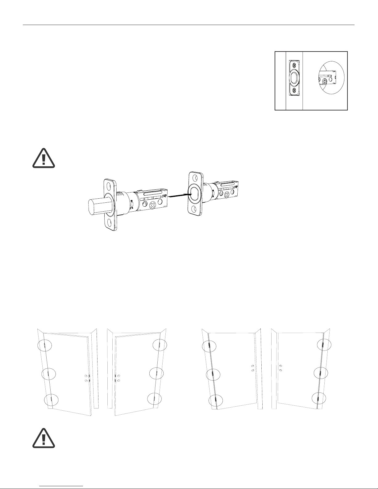
4. IDENTIFYING YOUR DOOR HANDING
Stand outside the door.
a.IfthehingesareontheleftyourdoorisLeftHanded(Figure4a).
b.IfthehingesareontherightyourdoorisRightHanded(Figure4b).
NOTE: Deadbolt Latch must be retracted when installing
NOTE: You are standing outside the door
INSTALLINGDEADBOLTLATCHSET
OUT SWING DOOR IN SWING DOOR
Figure4a
Left Handed Door
Hinges are on the left side
Left Handed Door
Hinges are on the left side
Right Handed Door
Hinges are on the right side
Right Handed Door
Hinges are on the right side
Figure4b
Figure3a
Deadbolt Latch Extended
Deadbolt Latch Retracted

Page5
NOTE: Deadbolt Latch must be retracted when installing
NOTE: You are standing outside the door
PREPARINGTHEINTERIORASSEMBLY
6. SET THE ENTRY SWITCH FOR LEFT OR RIGHT HANDED DOOR
a.Gentlymovetheswitchto“L”forLeftHandedDoor(Figure6a).
b.GentlymovetheSwitchto“R”forRightHandedDoor(Figure6b).
7. SET THE INTERIOR KNOB POSITION FOR LEFT OR RIGHT HAND HINGED DOORS
a.TheInteriorKnobgoesintheHorizontalpositionforLeftHandedDoors(Figure7a).
b.TheInteriorKnobgoesintheVerticalpositionforRightHandedDoors(Figure7b).
NOTE: Make sure deadbolt Latch is retracted
Right Handed Door
(Vertical)
Entry Switch
(Left or Right)
Left Handed Door
(Horizontal)
5. UNPACK THE INTERIOR ASSEMBLY
a.Removethebatterycoverbyslidingthecoverupward.
b.LocatethescrewsholdingtheMountingPlatetotheInteriorAssembly.Removethe
screwstoreleasetheMountingPlatefromtheInteriorAssembly.
Figure6a-b
Figure7a-b

Page6
9. SECURING THE EXTERIOR ASSEMBLY TO THE DOOR
a.Fromthesidemarked“Thissideagainst
door”,routetheControlWirethroughthe
rectangular slot in the Mounting Plate
(Figure9a).
b.PlaceMountingPlateagainstdoorwithtailpiecepassing
throughthecenterholeinthethreeholeset(Figure9b).
c. Secure the Mounting Plate to the Exterior Assembly using
two7/8”(22mm)Screws(Figure9c).
d.HandtightenwithaPhillipsScrewdriverleavinglooselyconnected(Figure9d).
e. Check that the Rubber Gasket is properly aligned and correct as necessary
(Figure9e).
f.Checkverticalalignmentofthelock(Figure9f).
g.TightensecurelywithahandheldPhillipsScrewdriver.DO NOT OVER TIGHTEN
10. OPTIONAL INSTALLATION
a.Usinga1/16”(2mm)drillbit,drillapilotholeinyourdoorusingthe
MountingPlateupperholeasaguide(Figure10a).
b. Insert one 3/4”(19mm)screwandtighten.
8. INSTALLING THE EXTERIOR ASSEMBLY
WorkwiththeDoorOpenforeasyaccess.
a. Unpack the Exterior Assembly. Use care to not scratch the green circuit board
during handling and installation.
b. Check that the Rubber Gasket is properly seated on the Exterior Assembly
(Figure8a-b).
c.InserttheExteriorAssemblyontothedoorwiththetailpiecegoingthroughthe
Deadbolt Latch Set cross shaped spindle connector in the VERTICAL POSITION.
RoutetheControlWirethroughthedoorovertheDeadboltLatchSet(Figure8c).
NOTE: Tailpiece must be
positioned vertically
INSTALLINGEXTERIORASSEMBLY
Right handed door view
Rubber
Gasket
Control
Wire
Tailpiece
(Vertical)
Latch
Hole
Mounting Plate
3/4”(19mm)screw
(OptionalInstallation)
7/8”(22mm)screws
Control Wire
Figure8a-b Figure8c
Figure10a
Figure9a-f
NOTE: Lock and unlock using the key to see if
the Deadbolt Latch is opening and closing easily.

Page 7
INSTALLINGINTERIORASSEMBLY
11. ATTACH THE CONTROL WIRE TO THE INTERIOR ASSEMBLY
a. Use care to attach the Control Wire male plug to the Interior Assembly female
socketconnector(Figure11a).
b. Do not force the Control Wire male plug into the Interior Assembly female
socketconnector(Figure11b).
c.TheControlWiremaleplughastwoalignmenttabsonthesmoothsideofthe
plugwhichisthetopoftheplug(Figure11c).
d.TheControlWiremaleplugisinsertedwiththesmoothsideupintotheInterior
Assemblyfemalesocketconnector(Figure11d).
12. ATTACH THE INTERIOR ASSEMBLY TO DOOR
a.PositiontheInteriorAssemblyoverthetailpieceandpushtheInteriorAssembly
againstthedoor(Figure12a).
b.Usingtwo5/16”(8mm)screws and one 1”(25mm)screw, attach
the Interior Assembly to the Mounting Plate. DO NOT OVER TIGHTEN SCREWS
(Figure12b).
5/16”(8mm)screws
1”(25mm)screw
NOTE: Lock and unlock using Interior Knob to see if the
latch is opening and closing easily.
Figure12a-b
Figure11a-d

Page 8
13. Installing Batteries
a.Insert4AAhighqualityAlkalinebatteriesintotheBatteryCompartmentinthe
directionnoted+/-ontheCompartment.TheLockwillbeep2times,thekeypad
willilluminateblue,andtheHoneywellbuttonwillashgreentwicetosignifythat
ithasreceivedpower(Figure13a).
b.SlidetheBatteryCoverdownintothetrackontheInteriorAssemblytocover
thebatteries(Figure13b).
14. Testing Lock
With the Door Open
a.TesttheLockusingtheInteriorKnob.Theboltshouldmovesmoothly.
b.TestthelockusingtheKeypad.Tolockpressandthenpress“1234”
to unlock.
INSTALLINGINTERIORASSEMBLY(CONT.)
Override
Access Key
Exterior Assembly Interior Assembly
Interior
Knob
Battery
Cover
Light Indicator
Keypad
NOTE: Do not touch the Keypad until the blue light turns off.
Do not use rechargeable batteries or non-alkaline batteries.
Figure13a-b
INSTALLATION OVERVIEW
Strike Plate
BatteryCover
Interior Assembly
Key
Exterior Assembly
Rubber Gasket
Mounting Plate
Latch
5/16”(8mm)screws
Optional
3/4”(19mm)
screw
3/4”(19mm)
screws
7/8”(22mm)screws
1”(25mm)Screw
Este manual sirve para los siguientes modelos
3
Tabla de contenidos
Otros manuales de Cerrar de Honeywell


