Home Sentinel VI 300 Manual de usuario
VIDEO
DOORPHONE
SYSTEM
OWNER’S
MANUAL
INSTALLATION AND OPERATION
BEFORE INSTALLING OR,
OPERATING THE SYSTEM,
PLEASE READ THIS MANUAL
MODEL: VI 300

TABLE OF CONTENTS
Section
Important Safety Instructions………………….................
Warning…………………………………………………….
FCC Class B Notice………………………………………..
Introduction............................……………...........................
System Contents........................……………........................
Features......................................................…………............
Identifying the Parts
Monitor ..........................…...…....………………………
Camera…………………………………………………..
Monitor Terminal Connections………………………….
Camera Terminal Connections………………………….
Installation
Monitor & Camera.........................….......……………....
Testing Units...............……...........………...............……
Installation Tips…………………………………..……..
Operation
Door Camera & Monitor…………….…………………..
Trouble Shooting Guide.................…..................…………..
Technical Specifications.......…....................……………......
Appendix 1 - Connecting a Magnetic Contact…………….
Appendix 2 - Connecting an Electric Door Strike…………
Page
1
2
3
4
4
5
6
7
8
9
10
11
11
12
13
14
15
16

IMPORTANT SAFETY INSTRUCTIONS
WARNING: TO REDUCE THE RISK OF FIRE OR ELECTRIC SHOCK, DO
NOT EXPOSE THIS APPLIANCE OR POWER ADAPTER TO WATER OR
MOISTURE
•Read Instructions – All the safety and operating instructions should be
read before operating this equipment. These instructions should be
retained for future reference
•Heed Warnings – All warnings on the equipment and in the operating
instructions should be adhered to. All instructions regarding care
and operation of this equipment should be followed.
•Power Sources – Equipment should only be connected to the power
supply specified in the operating instructions or as marked on
the equipment.
•Power-Cord Protection – Keep cable cords and plugs clear of other
objects, particularly at the point where they exit the equipment.
•Cleaning – Clean the equipment by wiping with a soft cloth,
(do not use any abrasive agents or water).
•Non-use Periods – Power cords should be unplugged from the outlet
when left unused for a long period of time.
•Object and Liquid Entry – Take care not to drop objects or liquids on
any part of the equipment.
•Damage Requiring Service – The unit should be serviced by a
qualified service personnel when:
- The power-supply cord or the plug has been damaged; or
- Objects have fallen, or liquid has been spilled onto the equipment; or
- The equipment has been exposed to rain; or
- The equipment does not appear to operate normally or exhibits a
marked change in performance; or
- The equipment has been dropped, and/or the enclosure has
been damaged
• Servicing – Do not attempt to service the appliance beyond
that described in the operating instructions. All other servicing should
be referred to a Qualified Distributor’s Service Personnel.
-1-

WARNING
CAUTION !
RISK OF ELECTRIC SHOCK. DO NOT OPEN.
CAUTION! TO REDUCE THE RISK OF ELECTRIC SHOCK, DO NOT REMOVE
COVER (OR BACK). NO USER-SERVICEABLE PARTS INSIDE.
REFER SERVICING TO QUALIFIED SERVICE PERSONNEL.
Explanation of two Symbols
The lightning flash with arrowhead symbol, within
an equilateral triangle, is intended to alert the user to
the presence of un-insulated "dangerous voltage" within
the product's enclosure that may be of sufficient magnitude
to constitute a risk of electric shock to persons.
The exclamation point within an equilateral triangle is
intended to alert the user to the presence of important
operating and maintenance (servicing) instructions in
the literature accompanying the appliance.
THE GRAPHIC SYMBOLS WITH SUPPLEMENTAL MARKING
ARE ON THE BOTTOM OF THE SYSTEM.
“WARNING – TO PREVENT FIRE OR SHOCK HAZARD, DO
NOT EXPOSE THE UNIT TO RAIN OR MOISTURE”
!
-2-

FCC CLASS B NOTICE
NOTE
This equipment has been certified and found to comply with the limits
regulated by FCC, EMC and LVD. Therefore, it is designed To
provide reasonable protection against interference and will not cause
interference with other appliance usage. However, it is imperative that
user follows this manual's guidelines to avoid improper usage which
may result in damage to the unit, electrical shock and fire hazard or
injury. In order to improve the feature functions and quality of this
product, the specifications are subject to change without notice from
time to time.
Note:
This equipment has been tested and found to comply with the limits
For a Class B digital device, pursuant to Part 15 of the FCC Rules.
These limits are designed to provide reasonable protection against
harmful interference in a residential installation. This equipment
generates, Uses and can radiate radio frequency energy and, if not
installed and used in accordance with the instruction, may cause
harmful interference to radio communications. However, there is no
guarantee that interference will not occur in a particular installation.
If this equipment does cause harmful interference to radio or
television reception, (which can be determined by turning the
equipment off and on), the user is encouraged to try to correct the
interference by one or more of the following measures:
•Reorient or relocate the monitor unit..
• Increase the separation between the monitor and camera.
• Connect the equipment on a separate outlet
• Consult the dealer or an experienced radio or television
technician for help.
-3-

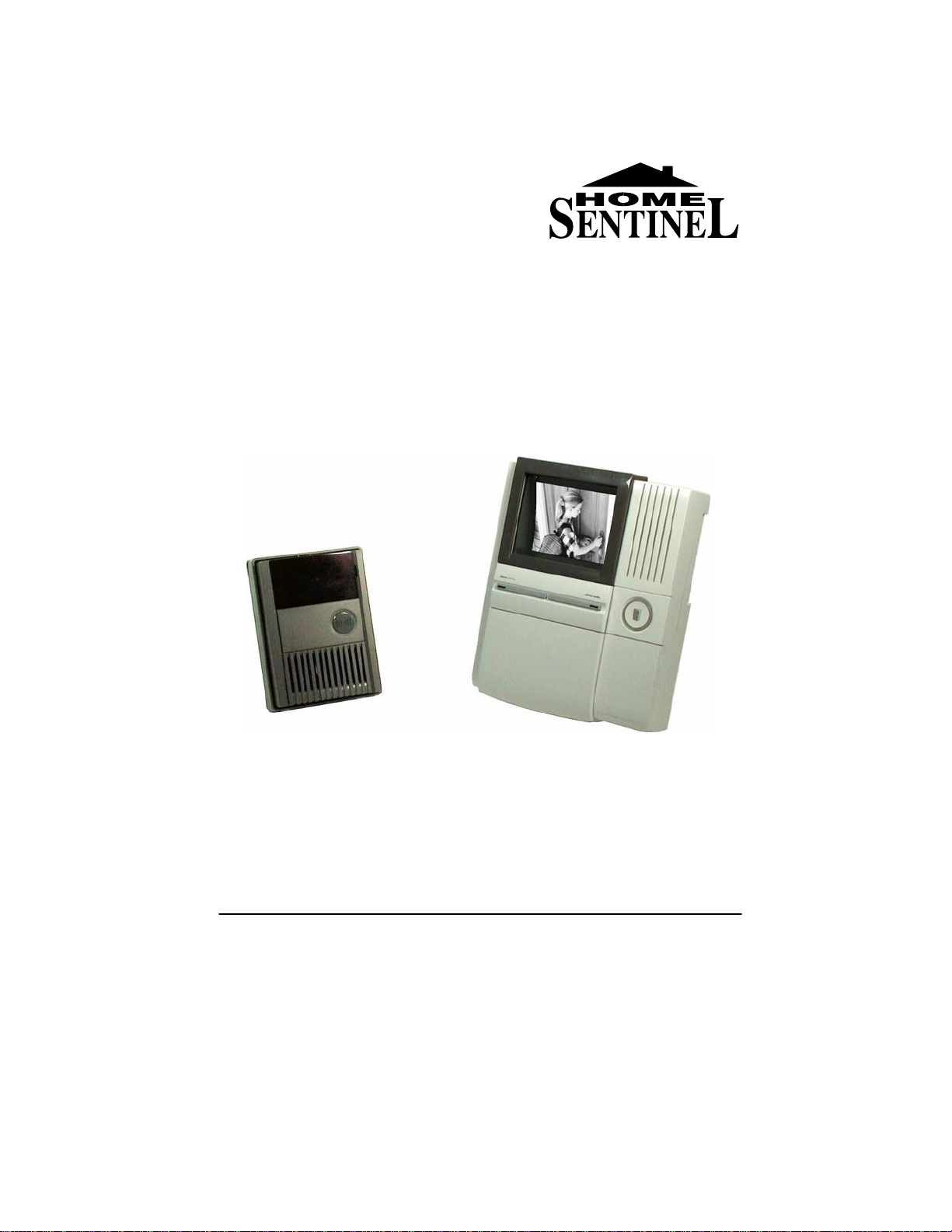
SYSTEM CONTENTS
VI 300 hands-free monitor VI 300 Weatherproof
door camera
Adaptor Screw Screw crank Wall mount plate
INTRODUCTION
Thank you for purchasing the Home Sentinel® Video Doorphone entry
system. This model allows you to identify and communicate with callers at
the door, from the security and convenience of any room in your home.
Visitors activate the system by pressing a call button on the outdoor camera,
which sounds a doorbell chime as well as turning on the inside video
monitor. A two way audio intercom then lets you speak with visitors after first
visually identifying them. It consists of a monitor station and an outdoor
camera unit.
Additional accessories such as an Electric Door Strike or magnetic contacts
can also be used on this system
For more information regarding the complete line of Home Sentinel®
products, please visit www.strategicvista.com
20 Meter, 2 conductor
18 gauge cable
-4-
Note: Please remove the transparent film from the camera and
monitor screen before using this system

FEATURES
MONITOR
• High definition 4" flat screen CRT
• Auto shut off after 30 seconds for unanswered calls and
90 seconds for answered calls
• Hands free audio intercom
• Brightness and sharpness controls
• Separate bell and audio volumes
• Remote door open function (requires optional electric
door strike)
• Door open/closed indicator (requires optional NC/NO
contact switch)
CAMERA
• Rugged weatherproof ABS (plastic) enclosure
• 1/3” B/W image sensor
• Extra wide angle lens (>120°)
• Backlit call button
• Audio intercom with adjustable volume
-5-

IDENTIFYING THE PARTS
6.69“
1. 4” B/W flat type CRT screen
Displays image delivered from the door camera
2. Hands free audio intercom
Emits audio from the door camera
3. Lock release button
Press to remotely unlock/open your door (requires optional electric
door release)
4. Door status light indicator
Door light illuminates to show whether the door is opened or closed
when an optional magnetic contact switch is used (NO/NC)
5. Speak-out button (one way)
When this button is pressed, you can talk and the visitor can only listen
in at the camera location
6. Speakerphone button (two way)
When this button is pressed it allows for two way conversation between
the monitor and the camera unit. Holding this button for 2 seconds turns
off the system.
7. Microphone
Picks up sound around the monitor
8. Brightness tuner
Allows you to control the brightness of the picture
9. Sharpness tuner
Allows you to control the sharpness of the picture
10. Bell volume tuner
Allows you to adjust the bell volume on the monitor
11. Speakerphone volume tuner
Allows you to adjust the the volume for two way conversation
12. Flip down panel with handy user instructions
A handy instruction sheet is available under the flip down panel
1
2
3
4
5
-6-
Monitor
170mm
4
2
3
12
7
6
5
1
8
9
10
11
208mm

1. 1/3” B/W CCD camera
A discreet high resolution black & white 1/3” CCD camera is located
behind the tinted cover
2. Infrared Emitters
Infrared Light Emitting Diodes (LED) will detect low light, thereby
giving you clear pictures at night at close range
3. Microphone
Picks up sound around the camera
4. Back-lit call button with chime
Press this button to ring the doorbell chime and activate the monitor.
The light around the call button will illuminate when the system has
power.
5. Speaker
Emits sound from the monitor location
6. Screw cover
This cover hides the screw that fastens the camera to the bracket
Camera
IDENTIFYING THE PARTS
-7-
133mm
100mm
6
5
4
1
3
2

IDENTIFYING THE PARTS
1. Power Adapter Connection - Remove the screw and the plastic cover
to connect the 24V DC power adapter from the back of the monitor to a
wall outlet using the supplied adapter.The terminal connection at the
monitor is a Y-terminal, and the +/- leads need to be inserted and
screwed into the corresponding contacts (refer to the DC 24V
illustration).
2. Door Camera - Connect the 2 conductor 18 gauge wire (20 meter/65
feet) from the terminals marked, “Door Camera” on the monitor to the
terminals on the camera unit, marked, “Monitor”
3. Door Status - Connect two wires from this terminal to an optional
magnetic contact for a door or window. A NO/NC contact can be
obtained at an electronics supply store.
Note: You’ll notice that the Door Status Terminal has been “shorted”
with a mini cable. This ensures that the Door Status indicator will
remain OFF when no magnetic contact is connected
4. Reserve – These terminals are not connected and should not be used
5. Lock Release - Connect the wires from this terminal to an optional
electronic door strike using a power supply (please see the diagram in
the Installation section of this manual). The Electronic Door Strike
accessory (model EDS300) can be purchased separately from Home
Sentinel®, please inquire with your vendor, or refer to
www.strategicvista.com for more details.
-8-
1
2
3
4
5
Monitor terminal connections
Tabla de contenidos
Otros manuales de Sistema de intercomunicación de Home Sentinel


