Hix N-680 Manual de usuario

Receiving.........................................................................................................................2
Installation .......................................................................................................................3
Home screen ...................................................................................................................4
Time & Temperature Adjustments....................................................................................5
Settings............................................................................................................................6
Presets .........................................................................................................................7-8
Cycle Count.....................................................................................................................9
Preferences ...................................................................................................................10
Pressure ....................................................................................................................... 11
Auto Shut Off Feature....................................................................................................12
Transfer Application..................................................................................................13-14
Maintenance..................................................................................................................14
Troubleshooting........................................................................................................15-17
Warranty ........................................................................................................................20
N-680 /N-880
15”x15” / 16”x20” Air Automatic Heat Transfer Machines
OWNER’S MANUAL
CONTENTS
BEFORE warranty repair you MUST get Prior Authorization
For Customer Service, Call 1-800-835-0606
or Visit www.hixcorp.com
N-880
N-680
70146 RV H_090220

2
RECEIVING
SHIPPING OR RETURNS
NOTE: Save all of your shipping/packing materials.
DO NOT RISK COSTLY SHIPPING DAMAGE!
SHIP ONLY IN ORIGINAL BOX.
1. Fasten machine to plywood shipping base with bolts provided.
2. Tie or tape handle securely to base.
3. Place in original box, and put side liner and top liner in place. Fold in
aps and seal the box. (Additional bottom boards, box and liners may
be obtained from your supplier for a nominal cost.)
UNPACKING
Remember to save all packing materials - including box, liner and board.
You may need these for shipping your machine or if a repair is necessary
in the future.
INSPECTION
Inspect your machine for hidden shipping damage. Contact the delivery
company immediately, should you nd damage.

3
INSTALLATION
1. Remove plywood shipping base bolts (see Aand B) and screw on feet
or afx self-adhesive rubber feet if provided.
CAUTION: Handle must be tied to base before moving or shipping.
ATTENTION: Immobiliser la poignée avant de trasporter.
2. Carefully cut tape/wrap holding machine closed.
3. Plug the machine into the correct grounded electrical outlet.
WARNING: When using an extension cord, use 12 or 14 ga.-3 conductor.
Maximum length, 25’ (7.762 m).
ATTENTION: Utiliser des ralonges d’au moins 12 à 14 ga - 3 phases;
longueur maximale de 7.7 mètres.
4. Supply a clean (void of oils) and dry (void of water) air source of 100-
125 P.S.I. (6.8-8.5 bar) to the 1/4” NPT air inlet located on the left side
panel (as viewed from the front) of the machine. Requires 1-1/2 to 2
CFM. It is strongly recommended that an external air lter and water
trap be installed at the machine’s air inlet connection. Compressed air
is dirty. It has ‘stuff’, primarily moisture, residues from oil and smoke and
whatever else is in the air. Compressors or ‘shop air’ may have ltered
air and/or an “AIR DRYER” after the compressor. IF your air is not ltered
and dried, YOU MUST FILTER THE AIR and REMOVE THE WATER
AND ‘STUFF’ FROM THE AIR, before putting it in most air operated
machines, including our press. There are small valves and ports that can
become blocked from moisture and residue in compressed air, causing
your press to malfunction. An external air lter and water trap must be
installed at the machine’s air inlet connection, if your air is not ltered.
Damage to the machine’s internal air operated components can occur
that will not be covered under warranty. Combination air lter/water
traps are available at any major hardware store or may be purchased
directly from HIX (part #71145). Supply airline to be 3/8” minimum I.D.
up to 25’ run from the compressor. Supply runs longer than 25’ from
the compressor requires a ½” I.D. airline.
INSTALLATION

4
HOME SCREEN
1. Turn on the machine by pushing the on/off switch.
Startup/Splash screen is displayed as the controller boots up.
Note: The current program number and the software revision of the control-
ler are displayed at startup. (The default settings are program number
P 7 for °F, P 8 for °C and software revision RV 1.0)
After boot up, the home screen is displayed showing the current heat platen
temperature and set cycle time. The heat indicating lamp is represented
by the snowake in the upper left corner of the display. The heat indicating
lamp will display anytime the heating element is heating and will cycle on
and off after the set temperature is reached to maintain set temperature.
Startup/Splash Screen
MACHINE PRESET
BUTTONS
ACCESS
SETTINGS MENU
TEMPERATURE
READOUT/SETTING
HEAT INDICATING
LAMP
TEMPERATURE
MODE
TIME
READOUT/SETTING TIME SCALE
HOME MENU SCREEN

5
TIME & TEMP. ADJUSTMENTS
ADJUST TEMPERATURE:
1. Touch the temperature readout on the display. “UP” ▲ and “DOWN” ▼
arrows will appear on the right side of the display and the temperature
value will start ashing and to indicate it is in set mode.
2. Press the “UP” ▲ or “DOWN” ▼ arrow to change the temperature
value. Holding down on an arrow will change the temperature in 1 de-
gree increments for 10 values; then change to 10 degrees incremental
changes.
3. Once the desired temperature value is set, either press the temperature
value to lock the set temperature or simply wait for 2 seconds and it
will lock in the new value automatically.
ADJUST CYCLE TIME:
1. Touch the time readout on the display. “UP” ▲ and “DOWN” ▼ arrows
will appear on the right side of the display and the cycle time value will
start ashing and to indicate it is in set mode.
2. Press the “UP” ▲ or “DOWN” ▼ arrow to change the cycle time value.
Holding down on an arrow will change the time in 1 second increments
for 5 values; then change to 10 seconds incremental changes.
3. Once the desired cycle time value is set, either press the time readout
to lock the cycle time or simply wait for 2 seconds and it will lock in the
new value automatically.
TIME ADJUSTMENT SCREEN
UP ARROW
DOWN ARROW
TIME
READOUT/SETTING
TEMPERATURE ADJUSTMENT SCREEN
TEMPERATURE
READOUT/SETTING
UP ARROW
DOWN ARROW
6
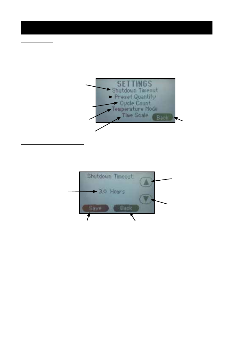
SETTINGS
SETTINGS:
1. Press the “?” on the upper right corner of the display on the Home
Menu Screen to access the settings menu.
2. Press the settings sub menu title to be adjusted.
SHUTDOWN TIMEOUT
The shutdown feature shuts off the heat to the press after a period of in-
activity.
NOTE: The factory default is set at 3.0 hours.
1. From the settings menu press the “Shutdown Timeout” sub menu title.
2. Press the “UP” ▲ and/or “DOWN” ▼ arrows to set the desired shut-
down time.
NOTE: Shutdown time adjusts in 1/2 hour intervals. Press the “Down” ▼
button until “Disable” is displayed will deactivate this setting.
3. Press “Save” to save the setting.
4. Press “Back” to return to the previous screen.
NOTE: After the shutdown time has elapsed with the press idle, the heating
element will stop cycling to maintain the set temperature and the
home screen will display “SHUTDOWN.” Touching the display or
closing the press will take the machine out of shutdown mode.
SETTINGS MENU SCREEN
RETURN TO
PREVIOUS
SCREEN
ADJUST SHUTDOWN TIMEOUT
SETTING
SET QUANTITY OF PRESETS
DISPLAYED
VIEW/RESET CYCLE COUNT
SET TEMPERATURE SCALE
PREFERENCE
SET TIME SCALE PREFERENCE
SHUTDOWN TIMEOUT ADJUSTMENT SCREEN
UP ARROW
DOWN ARROW
SHUTDOWN TIMEOUT
SETTING
SAVE SETTINGS RETURN TO PREVIOUS SCREEN

7
PRESETS
PRESET QUANTITY
Temperature presets can be stored in the memory for different trans-
fer settings. By default two presets are displayed. This setting can be
adjusted to display four presets.
1. From the settings menu press the “Preset Quantity” sub menu title.
2. Press the number of presets to be displayed on the home screen, either
“Two Presets” or “Four Presets.”
3. Press “Save” to save the setting.
4. Press “Back” to return to the previous screen.
NOTE: The “Toggle Two Presets” option will allow the operator to save two
different times in each preset (e.g. 2 seconds in Preset 1 and 8
seconds in Preset 2). Each time the handle is closed and the timer
times out then the controller will automatically “toggle” to the other
preset. This will allow the operator to set a short “pre-press” time.
The “No Presets” option, if selected, will remove the option for any
preset buttons to appear on the Home Menu Screen
TWO PRESET DISPLAY
ON HOME MENU SCREEN
FOUR PRESET DISPLAY
ON HOME MENU SCREEN
TWO PRESETS
DISPLAYED
FOUR PRESETS
DISPLAYED
SAVE SETTINGS RETURN TO PREVIOUS SCREEN
PRESET QUANTITY DISPLAYED PREFERENCE SCREEN
NO PRESETS
DISPLAYED
TOGGLE BETWEEN
PRESETS

8
PRESETS
STORING PRESETS:
NOTE: The factory default settings for all presets is set to 200°F and 10
seconds.
1. Set the desired temperature and/or cycle time using the temperature
and time adjustment instructions in this document.
2. Press and hold the desired preset location for two seconds. The con-
troller will beep and the preset location button will display in reverse
indicating the preset is stored in memory.
NOTE: Always refer to specic transfer recommendations for temperature,
time and pressure as instructed by the transfer manufacturer.
RECALLING PRESETS:
1. Press and release for approximately 1/2 second the preset button to
recall. The controller will beep and the preset location button will display
in reverse indicating the preset has been changed.
NOTE: The new set values will display for 1 second before the controller
starts adjusting the temperature or time to match the new set-
point.
PRESET
LOCATIONS
TEMPERATURE
SETTING
TIME
SETTING
HOME MENU SCREEN
PRESET 1 SELECTED
(two preset setting shown)
PRESET 2 SELECTED
(two preset setting shown)
PRESET
LOCATIONS
(press 1/2 second
to recall)

9
CYCLE COUNT
CYCLE COUNT
The cycle count feature counts the number of cycles that the machine
has undergone. A cycle is counted every time the countdown timer is
activated by closing the press.
NOTE: The cycle count will maintain the total count even if the power has
been turned off.
TO RESET THE COUNTER:
1. From the settings menu press the “Cycle Count” sub menu title.
2. Press “Reset.”
3. Press “Back” to return to the previous screen.
CYCLE COUNT/CYCLE COUNT RESET SCREEN
CYCLE COUNT
RESET TO ZERO RETURN TO PREVIOUS SCREEN

10
PREFERENCES
TEMPERATURE MODE
Temperature Mode controls which temperature scale is displayed on
the controller home screen.
F= Fahrenheit C= Celsius
TO CHANGE THE SCALE:
1. From the settings menu press the “Temperature Mode” sub menu
title.
2. Press the “UP” ▲ or “DOWN” ▼ arrows to select the preferred tem-
perature scale.
3. Press “Save” to save the setting.
4. Press “Back” to return to the previous screen.
TIME SCALE
The time scale setting adjusts how the time is displayed on the home
screen. There are three Time Scale display options available in the
Time Scale menu:
• MIN:SEC (Factory Default)
• SEC (Seconds)
• 1/10 SEC (1/10 Second Resolution)
TO CHANGE THE SCALE:
1. From the settings menu press the “Time Scale” sub menu title.
2. Press the “UP” ▲ and/or “DOWN” ▼ arrows to select the preferred
time scale.
3. Press “Save” to save the setting.
4. Press “Back” to return to the previous screen.
TEMPERATURE MODE PREFERENCE SCREEN
TEMPERATURE SCALE
PREFERENCE
SAVE SETTINGS RETURN TO PREVIOUS SCREEN
UP ARROW
DOWN ARROW
TIME MODE PREFERENCE SCREEN
TIME SCALE
PREFERENCE
SAVE SETTINGS RETURN TO PREVIOUS SCREEN
UP ARROW
DOWN ARROW
Este manual sirve para los siguientes modelos
1
Tabla de contenidos
Otros manuales de Herramientas de Hix


