Hitron HCH830M-2HBS Manual de usuario

P/ N
TITLE
SIZE
MATERIAL
UNLESS OTHERWISE SPECIFIED
ALL DIMENSIONS ARE IN MM.
- TOLERANCE
LABEL +/- 1.5
MANUAL +/- 3.5
ANGULAR +/- 0.5
FINISH
DATE
DRAWN
CHKED
APPROVALS
DESCRIPTION/MATERIAL
ITEM
A4
2
3
PRODUCTION RELEASE & REVISION
REV DESCRIPT'N/BUYER DWG No PARTS No. BY
NOTES
BIND : STAPLES-2
3.FINISH: -------------------
4.COLOR: TEXT-BLACK
5.SIZE: 140(+/-5)mm x 215(+/-5)mm R: 0.0
6.ANY CHANGE OR ALTERNATION MUST BE
APPROVED BY HITRON ENGINEERING.
MANUAL INSTRUCTION
50301507
A INITIAL / ALLBRAND -------------------- 50301507 S.A.PARK Y.W.YOON 05-02-M2
N.C.PARK
S.A.PARK
PARTS LIST
DWG No
---------------------------- REV.
SCALE
QTY
DO NOT SCALE
A
CHK DATE
140(+/-5)mm
215(+/-5)mm
09-07-M4
BUYER BRAND TYPE (Label: 50201073)
BRAND
MODEL No.
ADDRESS
120mm
30mm
ex) HITRON TYPE
Model No.: HCH830M-2HBS
HITRON SYSTEMS INC.
109-19 MAJEON-RI, SAMJUK-MYEON,
ANSUNG-CITY, KYUNGKI-DO, 456-881 KOREA
09-07-M4
AC/CA 24V ~ 60Hz Max. 25W
50301507
Please read this manual thoroughly before use and keep it handy for future reference.
Rev.0400908
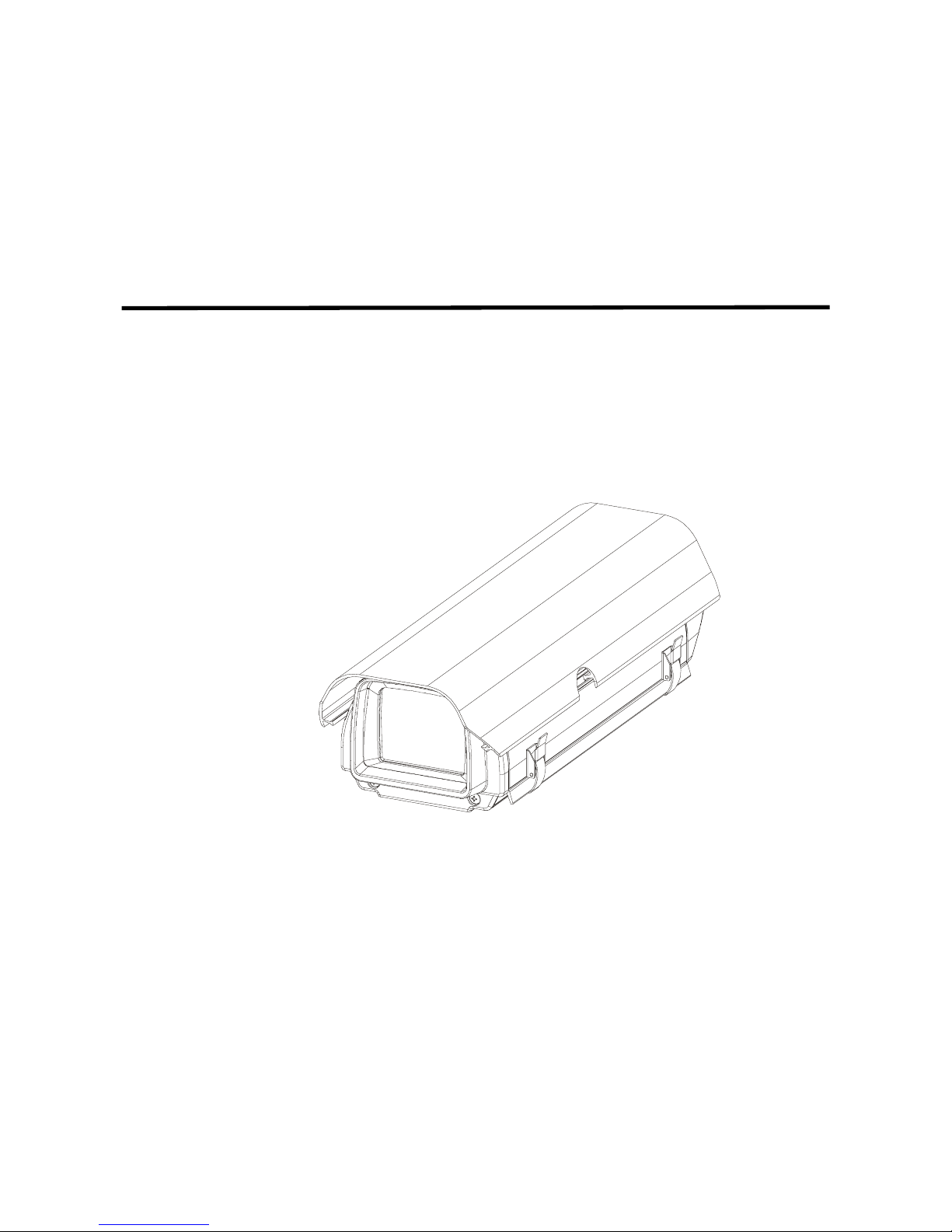
CAMERA HOUSING
CAMERA HOUSINGCAMERA HOUSING
CAMERA HOUSING
Series
SeriesSeries
Series
INSTALLATION MANUAL
10-Inch/12-Inch CAMERA
ENCLOSURES

ii
TABLE OF CONTENTS
1. CAMERA HOUSING SERIES INTRODUCTION
1.1 PURPOSE ............................................................................ 1
1.2 FEATURES........................................................................... 1
2. HOUSING INSTALLATION INTRODUCTIONS
2.1 CONTENTS OF PACKAGE …………………………………. 2
2.2 PREPARATION FOR INSTALLATION …………………….. 2
2.3 INSTALLATION OF OPTIONAL COMPONENTS ………... 4
2.3-1 Blower Kit Installation ………………………………………… 4
2.3-2 Heater Kit Installation ………………………………………… 5
2.3-3 Blower Kit with Heater Kit ……………………………….…… 7
2.4 CAMERA MOUNTING ………………………………………. 9
2.5 SUNSHIELD INSTALLATION............................................. 11
2.6 WALL BRACKET MOUNTING ...........................................11
2.7 MAINTENANCE.................................................................. 12
3. SPECIFICATIONS
3.1 CAMERA HOUSING SERIES SPECIFICATIONS .............13
3.2 SUNSHIELD (OPTIONAL).................................................. 14
3.3 HEATER (OPTIONAL)........................................................ 14
3.4 BLOWER (OPTIONAL) ......................................................14

1
1. CAMERA HOUSING SERIES INTRODUCTION
1.1 PURPOSE
The camera housing series are stylishly and functionally
designed enclosures for 1/2" and 1/3" CCD cameras with fixed
focal length or small zoom lenses. This manual describes how to
assemble the housing and its optional components, affix the
camera, and mount the assembly to a suitable surface.
1.2 FEATURES
The camera housing series includes the fallowing feature:
•Contemporary design
•Die-cast and extruded aluminum construction
•Adjustable mounting track
•Removable body for easy servicing
•Optional heater kit, blower kit and snap-on sunshield
components
•Indoor/outdoor applications
•Epoxy powder coating for corrosion resistance
•IP66 rated

2
2. HOUSING INSTALLATION INSTRUCTIONS
2.1 CONTENTS OF PACKAGE
Remove the camera housing from the carton and verify that it
was not damaged in shipment.
The package includes:
1. Camera housing (including screws and washers)
2. Optional accessories and hardware
(varies by specific model purchased.)
3. Desiccant bag
4. UNC 1/4"-20 machine screws
5. Manual
2.2 PREPARATION FOR INSTALLATION
This section contains comprehensive instructions for installing
the heater kit and blower kit for the camera housing series.
These kits are sold as add-on components or are available in a
pre-assembled package. The MODEL A(B)-HB is a 10(12)-inch
camera housing with an installed sunshield, heater and blower.
After unpacking and identifying the package contents, perform
the following steps to mount the camera in the housing:
1. Locate the following items which may be needed during
installation but are NOT supplied with the enclosure:
•Screwdriver
•Camera and camera cable
•Power supply

3
2.2 PREPARATION FOR INSTALLATION
2. If applicable, move the sunshield by sliding it forward on the
main housing unit. Set the sunshield aside until needed.
3. Unlatch the lid and open the upper body.
4. Before closing the housing, remove the desiccant bag from
the protective packaging and place the desiccant bag inside
the housing to absorb moisture.
5. Locate the gold, panhead 1/4"-20 UNC screws and set them
aside for later use.
6. Continue with installation of additional components as needed.
If no additional components are installed, continue to
instructions for camera mounting.
OPEN
UNLATCH
LID

4
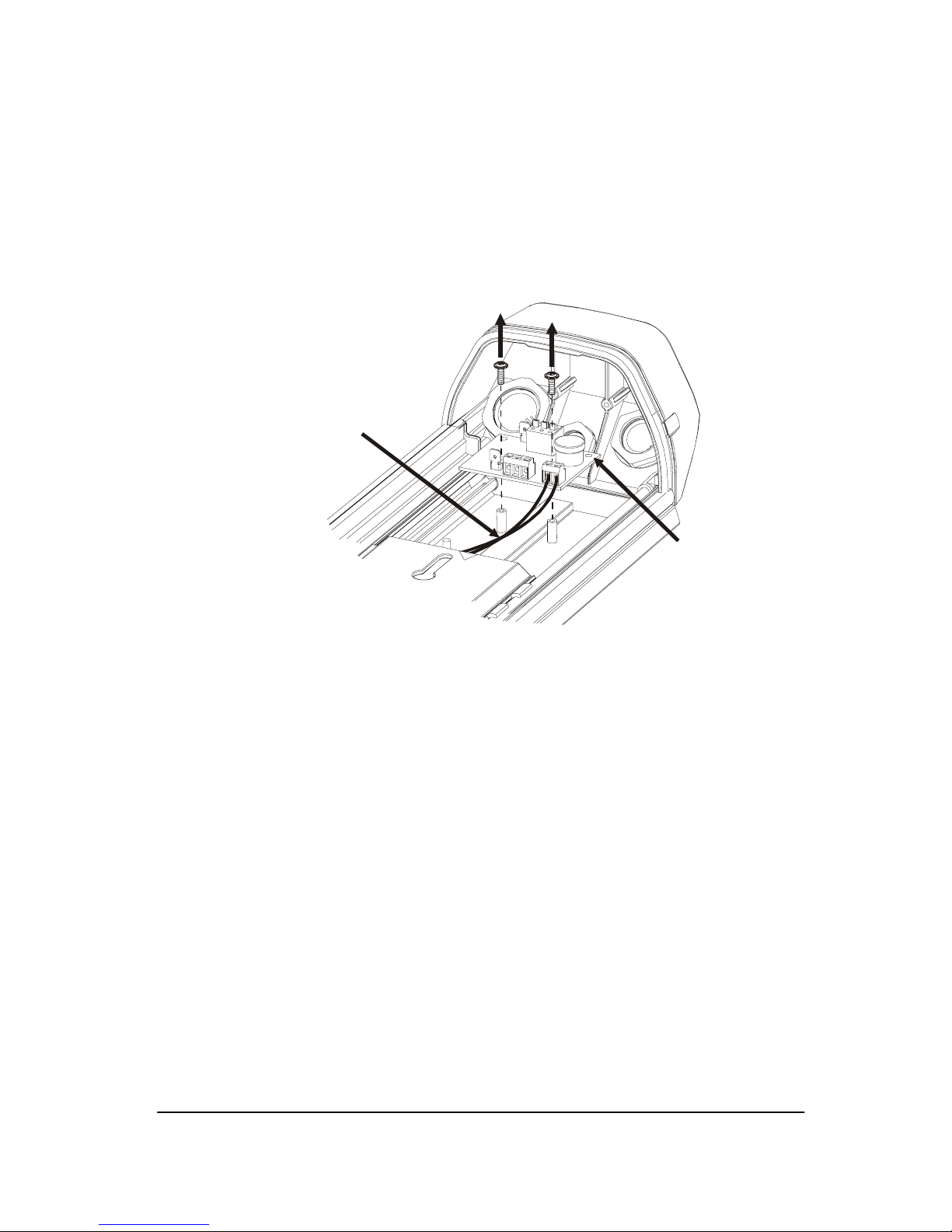
2.3 INSTALLATION OF OPTIONAL COMPONENTS
2.3-1 BLOWER KIT INSTALLATION
1. Mount the blower unit located two on the rear of the housing.
Align the hole and secure using the small Philips panhead
screw.
2. Mount the blower circuit board located on the lower body.
Align the holes and keep the wiring on the same side. Insert
the small Philips panhead screws and secure the assembly.
BLOWER UNIT
SMALL
PHILIPS
PANHEAD
SCREWS
SMALL
PHILIPS
PANHEAD
SCREWS

5
2.3 INSTALLATION OF OPTIONAL COMPONENTS
3. Connect the external power supply (not included) to the circuit
board. The recommended power supply is 24Vac, 50VA.
4. If adding a heater kit, see instructions for adding both the
blower kit and heater kit. If no other components will be
added, proceed to camera mounting instructions.
2.3-2 HEATER KIT INSTALLATION
1. Mount the heater unit in on the support rail on the lower body.
Align the tapped hole and secure the unit using the small
Phillips panhead screw.
24Vac Out
to Heater
24Vac Power
Supply Output
24Vdc Out
to Blower
24Vac Power
Supply Input
Ground Ground
(B+)
(Ground)
J3
J6J4J5
J1
LOWER BODY
SMALL PHILIPS
PANHEAD SCREW

6
2.3 INSTALLATION OF OPTIONAL COMPONENTS
2. Mount the heater circuit board on the lower body. Align the
holes and keep the wiring on the same side. Use the small
Phillips panhead screws to secure the assembly.
3. Connect the external power supply (not included) to the circuit
board. The recommended power supply is 24Vac, 50VA.
4. Continue with instructions for mounting the camera.
SMALL
PHILIPS
PANHEAD
SCREWS
24Vac Out
to Heater
24Vac Power
Supply Output
24Vac Power
Supply Input
Ground Ground
J6J4J5
J1
7
2.3 INSTALLATION OF OPTIONAL COMPONENTS
2.3-3 BLOWER KIT WITH HEATER KIT
1. Follow steps detailed previously to install the Blower Kit.
2. Using a small screwdriver, disconnect the wiring to the J1 and
J5 ports on the heater circuit board.
3. Replace the heater circuit board with the circuit board that is
wired to the blower. To do this, locate the two Philips
panhead screws on the heater circuit board. Unscrew them
and remove the board from the lower body of the housing.
Mount the blower circuit board located on the lower body.
Align the holes and keep the wiring on the same side. Use
the small Philips panhead screw to secure the assembly.
(Refer to drawing on next page.)
HEATER
CIRCUIT
BOARD
DISCONNECT
WIRING TO
J1 AND J5
PORTS
Tabla de contenidos
Otros manuales de Accesorios para cámaras de Hitron


