Hioki PD3259 Manual de usuario


i
Contents
Introduction .........................................................................1
Verifying Package Contents ..............................................1
Options (Sold Separately) ..................................................2
Safety Information .............................................................. 2
Operating Precautions ....................................................... 7
1 Overview 11
1.1 Overview and Features ................................. 11
1.2 Part Names and Functions ........................... 12
1.3 Battery Level ..................................................15
2 Preparing for Measurement 17
2.1 Measurement Process ..................................17
2.2 Attaching Color Spirals and Bundling
Cables Together ............................................18
2.3 Attaching the Magnetic Strap (Optional) ....19
2.4 Installing and Replacing Batteries ..............20
2.5 Inspecting the Instrument ............................21
2.6 Turning the Instrument On and Off ..............22
2.7 Attaching the Voltage Sensors to the
Circuit ............................................................. 23
2.8 Setting Up the Instrument in the
Measurement Location .................................26
3 Performing Measurement 27
3.1 Measuring Line Voltages in a 3-phase
Circuit ............................................................. 28
3.2 Checking Phase Order in a 3-phase
Circuit (Phase Detection Function) .............30
PD3259A981-00

ii
Contents
3.3 Measuring Frequency ...................................31
4 Convenient Uses 33
4.1 Power-on Options .........................................33
Auto power-off function ............................................. 35
Disabling the auto-power-off function .......................36
Switching the phase display (phase display
switching function) ....................................................37
Enabling and disabling the beep function ................. 38
Checking the version and serial number ..................39
4.2 Holding the Display .......................................40
Enabling and disabling the hold function ..................40
4.3 Turning On the Backlight ..............................41
Enabling and disabling the backlight ........................41
4.4 Displaying the Predicted State for a
3-phase Circuit ..............................................42
5 Specification 43
5.1 GeneralSpecification .................................43
5.2 InputSpecification andMeasurement
Specification ................................................ 44
Accuracy specification ............................................45
5.3 FunctionalSpecification .............................45
5.4 OtherSpecification .....................................46
6 Maintenance and Service 47
6.1 Repair, Inspection, and Cleaning .................47
6.2 Troubleshooting ............................................48
Error codes ...............................................................51


1
Introduction
Introduction
Thank you for choosing the Hioki PD3259 Digital Phase Detector.
To obtain maximum performance from the instrument, please read
this manual first, and keep it handy for future reference
Verifying Package Contents
Once you have received the instrument, verify that it has not
suffered any damage during shipment before using it.
Pay particular attention to the accessories, panel keys, and cables.
If damage is evident, or if it fails to operate according to the
specifications, contact your authorized Hioki distributor or reselle .
Confirm that these contents are provided
PD3259 Digital Phase Detector Accessories
LR6 (AA-size) alkaline batteries
× 4
Instruction
manual
Carrying
case
Spiral tubes
(black, red, blue, yellow)

2
Options (Sold Separately)
Options (Sold Separately)
The following options are available for this instrument. Contact your
authorized Hioki distributor or reseller when ordering.
Z5020 Magnetic Strap (p. 19)
The magnetic strap can be used to attach the instrument
to a wall, such as a metal surface.
Safety Information
This instrument is designed to conform to IEC 61010 Safety
Standards, and has been thoroughly tested for safety prior to
shipment. However, using the instrument in a way not described in
this manual may negate the provided safety features. Before using
the instrument, be certain to carefully read the following safety notes.
CAUTION
• Mishandling during use could cause damage to
the instrument. Be certain that you understand the
instructions and precautions in the manual before use.
• Individuals using an electrical measuring instrument for
the first time should be supervised by a technician who
has experience in electrical measurement.
Protective gear
WARNING
This instrument measures live lines. To prevent
electric shock, use appropriate protective insulation
and adhere to applicable laws and regulations.

3
Safety Information
Safety-related notations
In this manual, the risk seriousness and the hazard levels are
classified as follows
DANGER Indicates an imminent hazard that could lead to
serious injury or death.
WARNING Indicates a hazard that could lead to serious injury
or death.
CAUTION
Indicates a hazard that could lead to minor injury
or that could be expected to result in equipment or
other damage.
IMPORTANT
Indicates information related to the operation of the
instrument or maintenance tasks with which the
operators must be fully familiar.
Indicates a strong magnetic-field hazard
The effects of the magnetic force can cause
abnormal operation of heart pacemakers and/or
medical electronics.
Indicates a high-voltage hazard.
Warns that failure to verify safety or improper use of
the instrument could lead to electric shock, burns,
or death.
Indicates a prohibited action.
Indicates the action which must be performed.
*Additional information is presented below.
[ ] Names of items on screens are enclosed in
parentheses ([ ]).
MODE
(Bold font)
Alphanumeric characters shown in bold indicate the
characters that appear on the control keys.

4
Safety Information
Symbols displayed on the instrument
Indicates cautions and hazards. When the symbol is printed on
the instrument, refer to a corresponding topic in the Instruction
Manual.
Indicates an instrument that is completely protected by double
insulation and reinforced insulation.
Indicates the grounding terminal.
Indicates DC (Direct Current).
Indicates AC (Alternating Current).
Indicates the power supply’s “on” and “off” positions.
Symbols for various standards
Indicates the Waste Electrical and Electronic Equipment
Directive (WEEE Directive) in EU member states.
Indicates that the product conforms to regulations set out by the
EC Directive.
5
Safety Information
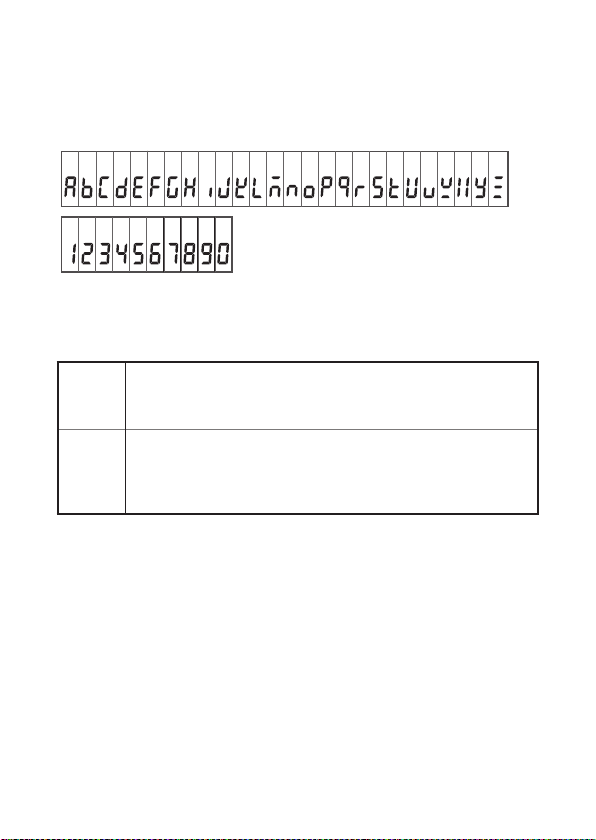
Characters in screen displays
The screen of this instrument displays characters in the following
manner.
1 2 3 4 5 6 7 8 9 0
A B C D E F G H I J K L M N O P Q R S T U V W X Y Z
Accuracy
We define measurement tolerances in terms of rdg. (reading) and
dgt. (digit) values, with the following meanings:
rdg.
(Reading or displayed value)
The value currently being measured and indicated on the
measuring instrument.
dgt.
dgt. (resolution)
The smallest displayable unit on a digital measuring instrument,
i.e., the input value that causes the digital display to show a “1”
as the least-significant digit

6
Safety Information
Measurement categories
To ensure safe operation of measurement instruments, IEC 61010
establishes safety standards for various electrical environments,
categorized as CAT II to CAT IV, and called measurement
categories.
DANGER
•Using a measuring instrument in an environment
designated with a higher numbered category than
that for which the instrument is rated could result in
a severe accident, and must be carefully avoided.
•Using a measuring instrument without categories in
an environment designated with the CAT II to CAT
IV category could result in a severe accident, and
must be carefully avoided.
This instrument conforms to the safety requirements for CAT IV 600 V
measuring instruments.
CAT II: When directly measuring the electrical outlet receptacles of the
primary electrical circuits in equipment connected to an AC electrical
outlet by a power cord (portable tools, household appliances, etc.)
CAT III: When measuring the primary electrical circuits of heavy equipment
(fixed installations) connected directly to the distribution panel, and
feeders from the distribution panel to outlets
CAT IV: When measuring the circuit from the service drop to the service
entrance, and to the power meter and primary overcurrent
protection device (distribution panel)
T
Outlet
CAT II
Internal wiring
Distribution panel
Service entrance
Service drop
CAT IV
Power meter
CAT III
Fixed installation
Tabla de contenidos
Otros manuales de Sensor de seguridad de Hioki


