ShenzhenHerewinTechnologyCo.,Ltd.
3
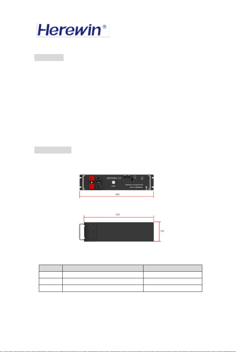
3.General Structure Description
Figure 2 Functional Description of the Front Panel
①SWITCH
The total battery switch, press the switch, turn on the battery output.
②CAPACITY indicator
Four white LEDs perform a four-segment SOC indication, with the LEDs from left to
right representing the SOC from low to high. For details on the definition of SOC, see
《Table 2: Correspondence Table between Battery LED and SOC 》
③ALRM indicator
Red LED flashing to show the battery has alarm, and lighting to show the battery is
under protection.
④RS485 indicator
Lighting to show RS485 had connected.
⑤CAN indicator
Lighting to show CAN had connected.
⑥CAN port
Follow CAN protocol, for output batteries CAN information. The CAN-1 and CAN-2
ports have the same pin assignments and functions.
⑦RS485 port
Follow RS485 protocol, for output batteries RS485 information. The RS485-1 and
RS485-2 ports have the same pin assignments and functions.
⑧Battery port+
The output port of battery positive, to connect the positive of the inverter.
⑨Battery port-
The output port of battery negative, to connect the negative of the inverter.