7
®
Heat Link
www.heatlink.com
HEP025RT
Installation, Operation, and Maintenance Manual
L6HEP025RT
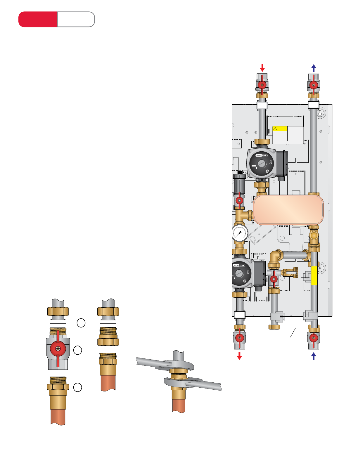
# Components Component Description Part Number (Qty.)
HEP025RT
1Single wall, brazed-plate heat
exchanger
The heat exchanger provides separation of the
primary and secondary loops.
2Primary pump
hydronic system when there is a call for heat
from the thermostat. Factory set to 3rd speed.
See pump curves below.
PUMP1558
3Secondary pump PUMP1558
4Electrical box Houses relays and wiring.
5Timer
6Terminal block
switch (opt.), and aux. contacts.
724Vac 20VA plug-in transformer Provides power to the panel electronics. PLINTR20VA
8
For pressure relief only. Furnished without a lever.
12.06 bar). Setting 50, 75, 125 and 150psi (3.45,
5.17, 8.61 and 10.34 bar).
This protects the system from thermal expansion
pressure buildup during times when reducing
to high inlet water pressure.
9Pressure gauge
The rear connection pressure gauge reads the
secondary loop pressure. May not be exactly as
shown.
Range: 0-60psi
10 Automatic air vent Automatic air vent purges air trapped in the
secondary loop. May not be exactly as shown. 79932
11
12
pre-set level (approx. 0.5 US gpm). Must be
piped in downstream of panel.
FLWSWTCH
13 Accessory pack Panel installation accessories.*
i Mounting screw Panel mounting screws. (×4)
ii Washers for installation of adapters, plus (4)
spares. NTRWSH34 (×10)
iii Adapters for expansion tank, and pressure relief
piping. (×2)
iv Zone valve used to isolate the panel from the
(×4)
14 Optional cover Powder coated cover PC2319CVR
*Contact your HeatLink representative if the accessory pack is missing in whole or in part.
Panel Components