HALaser Systems HALdrive X20 Manual de usuario

HALdrive X20
XY3-100 to Analogue Converter
Users Manual
© 2020-2021 by HALaser Systems
1

Table of Contents
1 Copyright.........................................................................................................................................................................................................3
2 History..............................................................................................................................................................................................................
3 Safety................................................................................................................................................................................................................5
Overview.........................................................................................................................................................................................................6
.1 Features.................................................................................................................................................................................................6
5 HALdrive Board And Connectors.........................................................................................................................................................7
5.1 Scanner Signals...................................................................................................................................................................................8
5.2 Galvo X Signals....................................................................................................................................................................................8
5.3 Galvo Y Signals....................................................................................................................................................................................8
6 HALdrive OEM Board And Connectors...........................................................................................................................................10
6.1 HALdrive OEM for Z-Channel...................................................................................................................................................11
7 Initial Operation.........................................................................................................................................................................................12
APPENDIX A – Wiring between HALdrive and E1701D..............................................................................................................13
APPENDIX B – Wiring between HALdrive and E1803D..............................................................................................................1
APPENDIX C – IDC connector pin numbering..................................................................................................................................15
APPENDIX D – XY3-100 protocol description.................................................................................................................................16
APPENDIX E – Board dimensions...........................................................................................................................................................17
2

1 Copyright
This document is © by HALaser Systems.
E1701 boards, their hardware and design are copyright / trademark / legal trademark of HALaser Systems.
E1803D boards, their hardware and design are copyright / trademark / legal trademark of HALaser Systems.
HALdrive and HALscan, their hardware and design are copyright / trademark / legal trademark of HALaser
Systems.
XY3-100 is copyright/trademark by Laser Industry Association International.
All other names / trademarks are copyright / trademark / legal trademark of their respective owners.
3

2 History
Date Changes in document
0 /2022 Maximum current for galvo outputs speci=ed
12/2021 Pinout description extended, power supply wiring description added
06/2021 XY3-100 certi=ed logo added
05/2021 Added pinout and description of HALdrive OEM
0 /2021 Wiring schemes for E1701D and E1803D added
10/2020 Added description for 10V hardware variant
07/2020 Added section for initial operation
06/2020 Initial version

3 afety
The hardware described within this document is designed to control a laser scanner system. Laser radiation
may effect a person's health or may otherwise cause damage. Prior to installation and operation compliance
with all relevant safety regulations including additional hardware-controlled safety measures has to be
secured. The client shall solely be responsible to strictly comply with all applicable and relevant safety
regulations regarding installation and operation of the system at any time.
Beside of that some laser equipment can be damaged in case it is controlled with wrong signals or signals
outside a given speci=cation. Thus it is highly recommended to check the output generated by this hardware
using e.g. an oscilloscope to avoid problems caused by wrong con=gurations. This should be done prior to
putting a system into operation for the =rst time, whenever some parameters have been changed or whenever
any kind of software update was installed.
The hardware described here is shipped without any cover and without prefabricated equipment for electric
installation. It is intended to be integrated in machines or other equipment. It is not a device for use "as is", but a
component which is intended to be used as part of a larger device, e.g. for integration in a machine with own
housing or within an electrical cabinet. Prior to operation compliance with all relevant electric /
electromagnetic safety regulations including additional hardware-controlled safety measures has to be
secured. The client shall solely be responsible to strictly comply with all applicable and relevant regulations
regarding installation and operation of the system at any time.
The hardware described here is an electrostatic sensitive device. This means it can be damaged by common
static charges which build up on people, tools and other non-conductors or semiconductors. To avoid such a
damage, it has to be handled with care and including all relevant procedures (like proper grounding of people
handling the hardware, shielding/covering to not to let a person touch the hardware unwanted, proper
packaging in ESD-bags, ...). For more information please refer to related regulations and standards regarding
handling of ESD devices. The EMC Directive (201 /30/EU) does not apply to this hardware as it is not intended
for an end user (a person without knowledge of EMC) and as it is not otherwise made available on the market.
The Low Voltage Directive (201 /35/EU) does not apply to this hardware as the voltage supply is below the
50V AC / 75V DC limit.
This document describes the HALdrive digital XY3-100 to analogue converter hardware but may contain errors
or may be changed without further notice.
5

4 Overview
This document describes the HALdrive X20 converter board, its electrical characteristics and usage.
This board is designed to receive digital XY3-100 scanner controller signals and to convert them to 2x
synchronous analogue output signals. So it acts as some kind of converter between two different signal types
for controlling scanning systems/scanheads.
This board is not a ready-to-use device but a component which is intended to be integrated in larger devices or
to be operated with an own housing.
4.1 Features
The HALdrive converter board provides the following features:
•accepts 2D input signals in XY3-100 format (X and Y position data, Z is ignored if available)
•synchronous output of analogue X and Y position data in -5V..5V or -10V..+10V voltage range
•20 bit output resolution
•100 kHz sampling/output frequency
•available in variants for +-5V output and +-10V output
•instant-on, so there is no boot-up time until the device is available
6

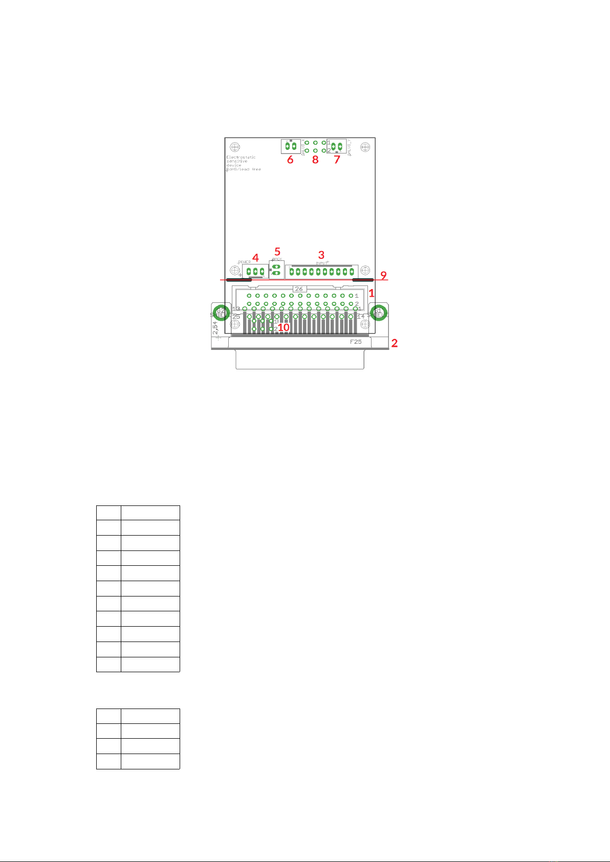
5 HALdrive Board And Connectors
The board provides the following connectors:
1. XY3-100 interface for power supply and scanner input signals (as described below)
2. Galvo-X analogue output with +-5V / +-10V and GND pin (available only on hardware variant A)
3. Galvo-Y analogue output with +-5V / +-10V and GND pin (available only on hardware variant A)
. 2,5 mm 6pin connector for Galvo-X and Galvo Y analogue signals, available only with hardware variant
B, replaces the JST B2B-PH-K-S connectors of hardware variant A
Pin ignal Description
1 NC Unused and reserved for future use, do not connect!
2 NC Unused and reserved for future use, do not connect!
3 Galvo-Y analogue output with voltage possible in range +-5V .. +-10V
Galvo-X analogue output with voltage possible in range +-5V .. +-10V
5 GND Common ground for Galvo-X
6 GND Common ground for Galvo-Y
7

5. Optional separate power supply input pin, when not provided via connector (1) here +-15V can be fed
in. The two second pins are for -15V, the two middle pins are for GND and the two right pins are for
+15V power input.
When no power supply with symmetric/bipolar outputs is available, it is possible to combine two
standard power supplies, here GND of the =rst power supply has to be connected with +V of the
second power supply and with the GND-pins of the HALdrive:
5.1 canner ignals
The white 26 pin connector expects the XY3-100 position signals and the power supply for the HALdrive board:
Upper
Row
Of
Pins
ignal Voltage Remarks Lower
Row
Of
Pins
ignal Voltage Remarks
1A-
XY3-100-
compatible signals
2A+
XY3-100-
compatible signals
3B- 4B+
5C- 6C+
7D- 8D+
9 10
11 12
13 1
15 16
17 +V +15V
Power supply from
scanner card
18 +V +15V
Power supply from
scanner card
19 +V +15V 20 GND GND
21 GND GND 22 GND GND
23 -V -15V 24 -V -15V
25 -V -15V 26
When the HALdrive is used together with the E1803D scanner controller card, a direct 1:1 connection can be
established between the white, 26 pin scanner signal connector of the E1803D controller and this connector.
Then power has to be supplied via the three screw-connectors of the E1803D (for details please refer to
manual of E1803D scanner controller card).
5.2 Galvo X ignals
5.3 Galvo Y ignals
On hardware variant A: These connectors are male 2 mm, 2 pin JST connectors of type B2B-PH-K-S which can
be used together with female connectors of type JST PH2P BU. They provide analogue signals synchronous to
the XY3-100 position signals.
For the +-5V hardware variant: Pin 1 works in range -5V .. +5V. Pin 2 is connected to GND.
8

For the +-10V hardware variant: Pin 1 works in range -10V .. +10V. Pin 2 is connected to GND.
On hardware variant B: a 6 pin, 25 mm header, to be used with an IDC connector, for the pinout please refer
the connectors overview above.
The maximum current to be pulled out of each of the outputs should never exceed 20 mA.
9
6 HALdrive OEM Board And Connectors
The HALdrive OEM is a customisable version of the standard HALdrive which is available to hardware
manufacturers in larger batches and where the types of connectors/inputs/outputs to be used can be chosen.
There are currently three different ways and connectors available as input for XY3-100 control data and two
different connectors and signal types as output for the received X and Y position data:
1. XY3-100 interface for power supply and scanner input signals on IDC-connector with standard pinout
as described in section “5.1 Scanner Signals” above, can be used instead of connectors (2) or (3), ( ) and
(5)
2. XY3-100 interface for power supply and scanner input signals on standard D-SUB25-connector with
pinout according to the XY3-100 standard, can be used instead of connectors (1) or (3), ( ) and (5); this
connector also can be used as mechanical connection to the housing of a device
3. Alternative connector for scanner input signals, can be equipped with a JST PH10P type connector
instead of (1) or (2) and provides the following pinout for XY3-100 control signal input:
Pin ignal
1 GND
2 GND
3 Y- (D-)
Y+ (D+)
5 X- (C-)
6 X+ (C+)
7 CLK- (B-)
8 CLK+ (B+)
9 SYNC- (A-)
10 SYNC+ (A+)
. Alternative connector for power supply, can be equipped with a JST PH3P type connector instead of
(1), (2) or (10) and provides the following pinout for power supply input:
Pin ignal
1 +15V
2 GND
3 -15V
10
Otros manuales para HALdrive X20
1
Tabla de contenidos
Otros manuales de Convertidor de medios de HALaser Systems


