
Hagie DTS 10 Manual de usuario

CONTENTS
5 - DASH / AUTO
Covers Machine Serial Numbers: DTS10 17001-17500 Part No. 493713
© 2016-18 Hagie Manufacturing Company. Clarion, Iowa USA Rev. 17G180406
1 – INTRODUCTION
A Word From Hagie Manufacturing Company ...................................................................1-1
About This Manual .............................................................................................................1-1
Safety Messages Used In This Manual .............................................................................1-1
Service and Assistance ......................................................................................................1-2
Product Warranty ...............................................................................................................1-2
Identification .......................................................................................................................1-2
Specifications .....................................................................................................................1-5
2 – SAFETY AND PRECAUTIONS
Intended Use ......................................................................................................................2-1
Safety Precautions .............................................................................................................2-1
Seat Belt ............................................................................................................................2-6
Rotating Beacon ................................................................................................................2-6
Emergency Stop ................................................................................................................2-7
Emergency Exit ..................................................................................................................2-7
Fire Extinguisher ................................................................................................................2-8
First Aid Kit .........................................................................................................................2-8
Roll-Over Protection Structure (ROPS) .............................................................................2-9
Safety Decals ...................................................................................................................2-10
3 – CAB
Seat - Operator (Standard) ................................................................................................3-1
Seat - Operator (Premium) ................................................................................................3-4
Seat - Instructor .................................................................................................................3-6
Operator’s Station ..............................................................................................................3-6
Machine Display ...............................................................................................................3-31
4 – ENGINE AND DRIVE SYSTEMS
Engine - Starting ................................................................................................................4-1
Engine Aftertreatment - Final Tier 4 ...................................................................................4-3
Hydrostatic Drive ..............................................................................................................4-10
All-Wheel Steer (AWS) ....................................................................................................4-15
5 – HYDRAULIC SYSTEMS
Hydraulic System Components ..........................................................................................5-1
Reversible Fan - Variable Pitch .........................................................................................5-4
Tread Adjustment - Hydraulic ............................................................................................5-6
Ladder ................................................................................................................................5-8
6 – ELECTRICAL SYSTEMS
Batteries .............................................................................................................................6-1
Battery Disconnect Switch .................................................................................................6-2

Fuses and Relays ..............................................................................................................6-4
Fuse and Relay Ratings .....................................................................................................6-8
Video Camera Input Connections ....................................................................................6-11
7 – SPRAY SYSTEMS
Spray Booms .....................................................................................................................7-1
Spray Boom - Rear ..........................................................................................................7-12
Solution System Components ..........................................................................................7-14
Solution System - Operation ............................................................................................7-23
Fence Row Applicator ......................................................................................................7-26
Filling Your Solution Tanks ..............................................................................................7-27
Draining Your Solution Tanks ..........................................................................................7-29
Rinse System ...................................................................................................................7-31
Foam Marker System .......................................................................................................7-35
Eductor System ................................................................................................................7-38
Modular Injection System .................................................................................................7-42
Application .......................................................................................................................7-51
8 – MAINTENANCE AND STORAGE
Service - Fluids ..................................................................................................................8-1
Service - Filters ................................................................................................................8-10
Service - Lubrication ........................................................................................................8-20
Service - Engine Drive Belt ..............................................................................................8-22
Service - Bolt Torque .......................................................................................................8-22
Service - Toe-In ...............................................................................................................8-25
Service - Miscellaneous ...................................................................................................8-27
Service Intervals ..............................................................................................................8-32
Storage ............................................................................................................................8-35
9 – MISCELLANEOUS
Transporting .......................................................................................................................9-1
Lifting Your Machine ..........................................................................................................9-4
Air Suspension Exhaust .....................................................................................................9-5
Viscous Clutch Fan ............................................................................................................9-6
Hand Wash System ...........................................................................................................9-8
Electric Hood ......................................................................................................................9-9
Front End Access .............................................................................................................9-11
Tread Adjustment - Manual ..............................................................................................9-12
Tall Crop Package - Installation .......................................................................................9-14
Troubleshooting ...............................................................................................................9-21

1-1
5 - DASH / AUTO
SECTION 1 – INTRODUCTION
A WORD FROM HAGIE
MANUFACTURING COMPANY
Congratulations on the purchase of your
DTS10 Sprayer! Read this operator’s manual
and become familiar with operating procedures
and safety precautions before attempting to
operate your sprayer.
As with any piece of equipment, certain
operating procedures, service, and maintenance
are required to keep your machine in top running
condition. We have attempted herein to cover all
of the adjustments required to fit varying
conditions. However, there may be times when
special care must be considered.
NOTE: The operator is responsible for
inspecting the machine and having parts
repaired or replaced when continued use
of the product causes damage or
excessive wear to other parts.
Hagie Manufacturing Company reserves the
right to make changes in the design and material
of any subsequent sprayer without obligation to
existing units.
Thank you for choosing a Hagie sprayer and
we ensure you of our continued interest and
support in its optimal performance for you. We
are proud to have you as a customer!
ABOUT THIS MANUAL
This manual will aid you in the proper
operation and service of your machine. It is the
responsibility of the user to read the operator’s
manual and comply with the correct and safe
operating procedures, as well as maintain the
product according to the service information
provided in the Maintenance and Storage
Section elsewhere in this manual.
Photographs and illustrations used in this
manual are of general nature only. Some of the
equipment and features shown may not be
available on your machine.
Information described in this manual was
correct at the time of printing. Because of Hagie
Manufacturing Company’s continuous product
improvement, certain information may not be
included in this manual. To obtain the most
current operator’s manual for your machine,
please visit www.hagiehelp.com.
Keep this manual in a convenient place for
easy reference. This manual is considered a
permanent fixture of the product. In the event of
resale, this manual must accompany the
machine.
If you do not understand any part of this
manual or require additional information or
service, contact your local John Deere dealer for
assistance.
SAFETY MESSAGES USED IN
THIS MANUAL
The following safety messages found
throughout this manual alert you of situations
that could become potentially dangerous to the
operator, service personnel, or equipment.
NOTICE
Any pictures or illustrations contained
within this manual that depict situations
with shields, guards, rails, or lids
removed are for demonstration only.
Keep all shields and safety devices in
place at all times.
DANGER
This symbol indicates a hazardous
situation which, if not avoided, will result
in serious injury or death.

SECTION 1 –
INTRODUCTION
1-2
NOTE: A “Note” is intended to make special
mention of, or remark on.
SERVICE AND ASSISTANCE
Please contact your local John Deere
dealer for service and assistance.
PRODUCT WARRANTY
Please contact your local John Deere
dealer for further information.
IDENTIFICATION
Each machine is identified by means of a
frame serial number. This serial number
denotes the model, year in which it was built,
and the number of the sprayer.
For further identification, the engine,
solution pump, and hydraulic pumps each
have serial numbers, and the planetary
wheel motor/hubs have identification plates
that describe the type of mount and gear
ratio.
To ensure prompt, efficient service when
ordering parts or requesting service repairs,
record the serial numbers and identification
numbers in the following spaces provided.
Machine
The machine serial number is stamped on
the front right-hand side of frame (behind the
front leg).
WARNING
This symbol indicates a potentially
hazardous situation which, if not
avoided, could result in moderate/
serious injury or death.
CAUTION
This symbol indicates a potentially
hazardous situation which, if not
avoided, may result in minor or
moderate injury. It may also be used to
alert against unsafe practices.
NOTICE
This symbol indicates operator
awareness which, if not avoided, may
result in personal or property damage.
NOTICE
Reference to right and left-hand used
throughout this manual refers to the
position when seated in the operator’s
seat facing forward.
Machine Serial Number
-Typical View
Serial No. _______________________
1-3
SECTION 1 –
INTRODUCTION
Engine
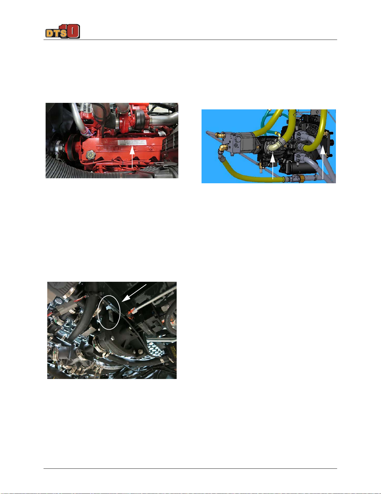
The engine has an identification plate
mounted on top of the engine that provides
engine serial number, as well as other
manufacturer information. Refer to your
Parts Manual for specific part number.
Solution Pump
The solution pump has an identification
plate mounted on the side of pump that
provides pump serial number, as well as
other manufacturer information. Refer to your
Parts Manual for specific part number.
Hydraulic Pumps
The PC and Drive Pumps each have an
identification plate mounted on the side of
pump that provides pump serial number, as
well as other manufacturer information. Refer
to your Parts Manual for specific part
number.
Wheel Motor/Hubs
Each wheel motor/hub assembly has an
identification plate mounted on the rear side
of the hub that provides serial number, as
well as other manufacturer information,
including gear ratio. Refer to your Parts
Manual for specific part number.
Engine Identification Plate
-Typical View
Serial No. _______________________
Solution Pump Identification Plate
* View shown from beneath machine
-Typical View
Serial No. _______________________
Hydraulic Pumps
-Typical View
________________________ PC Pump
________________________ Drive Pump
•PC
Pump
•Drive
Pump

SECTION 1 –
INTRODUCTION
1-4
Wheel Motor/Hub Assembly
-Typical View
_________________________ Right Front
_________________________ Right Rear
_________________________ Left Front
_________________________ Left Rear

1-5
SECTION 1 –
INTRODUCTION
SPECIFICATIONS
NOTE: Dimensions on your machine may vary, depending on tire size.
Detail Description Specification
AOverall Sprayer Height (from top of cab)
NOTE: Overall machine height dimension does not include the cab-
mounted rotating beacons or the optional GPS unit.
149.5” (379.3 cm) **
B Raised Transom Height 150.8” (383.0 cm) **
C1 Transom Height - Fully Raised 106” (269.2 cm)
C2 Transom Height - Fully Lowered 40” (101.6 cm)
C3 Transom Lift Range (C1 minus C2) 66” (167.6 cm)
D Static Loaded Hub Height 28.6” (72.6 cm) **
EWheel Base 139.4” (354.1 cm)
F Sprayer Length
NOTE: Overall machine length does not include the optional rear boom. 326” (828.0 cm)
GWidth (booms folded) 156” (396.2 cm)
H Frame Clearance 72” (182.9 cm) **
ILower Leg Clearance 23” (58.4 cm) **
J Tread Width* In = 120” (304.8 cm) **
Out = 160” (406.4 cm) **

SECTION 1 –
INTRODUCTION
1-6
* Tread width is measured from center of tire at
ground.
** Refer to “Tire Specifications” provided else-
where in this section for a complete listing of tire
options when configuring machine specifications
on your model.
General Information
•Frame Type: 3 x 8” (7.6 x 20.3 cm)
modular platform frame
•Suspension: 4-wheel, individual, auto
air-ride
•Shipping Width: 156”/396.2 cm
(from outside of each solution tank)
•Approximate Dry Weight:
18,500 lbs./8,391 kg
NOTICE
Because Hagie Manufacturing
Company offers a variety of options, the
illustrations in this manual may show a
machine equipped other than standard.
Height and weight do not consider
options. Values may vary, depending on
available equipment.

1-7
SECTION 1 –
INTRODUCTION
Spray System GPS Specifications
-If Equipped
NOTE: Dimensions on your machine may vary, depending on tire size.
Detail Description Specification
AWheel Base 139.4” (354.1 cm)
B Static Loaded Hub Height 28.6” (72.6 cm)
COverall Sprayer Height (from middle of GPS unit) 152.1” (386.3 cm)
D Length
(from front of boom spray tips to center of GPS unit)
114” (289.6 cm)
ELength (from center of GPS unit to center of rear hub) 97” (246.4 cm)

SECTION 1 –
INTRODUCTION
1-8
Settings and Calibration
Record settings and calibration values
used in the following spaces provided when
programming your spray system console.
Refer to this information for future reference.
Circle the selected setting on the spray system console for the following options:
Record calculated calibration values in the spaces provided below.
Units • US (Acres) • SI (Hectares) • Turf
(1,000 sq. ft./
92 sq. m)
Speed
Sensor
• SP1 (Wheel Speed) • SP2 (Radar/GPS)
Control Type • Liquid Spray • Gran 1
(Single Belt
Bed)
• Gran 2
(Split Belt
Bed/Single
Encoder)
• Gran 3
(Split Belt
Bed/Dual
Encoders)
• Spinner RPM
Control
Valve Type • Standard
Valve
•Fast Valve • Fast Close
Valve
• Pulse Width
Modulated
Valve
• Pulse Width
Modulated
Close Valve
Speed Cal Section
Widths
Meter Cal Rate Cal Valve Cal Tank Volume
1. 1. 1. 1. 1. 1.
2. 2. 2. 2. 2.
3. 3. 3. 3. 3.
4. 4. 4. 4. 4.
5. 5. 5. 5. 5.
6.
7.
8.
9.
10.
Otros manuales para DTS 10
3
Tabla de contenidos
Otros manuales de Pistola pulverizadora de pintura de Hagie

Hagie
Hagie STS 10 Manual de usuario

Hagie
Hagie STS 10 Combo Manual de usuario

Hagie
Hagie UpFront STS 14 Combo Manual de usuario

Hagie
Hagie STS12i Combo Manual de usuario

Hagie
Hagie STS/DPS Series Manual de usuario

Hagie
Hagie STS12i Combo Manual de usuario

Hagie
Hagie UpFront STS 16 Manual de usuario

Hagie
Hagie DTS 10 Manual de usuario

Hagie
Hagie SmarTrax 2100 Series Manual de usuario

Hagie
Hagie STS 10 Combo Manual de usuario


