Hach POLYMETRON 8544 Manual de usuario

DOC024.98.93128
POLYMETRON Model 8544
12/2016, Edition 1
User Manual
Manuel d'utilisation

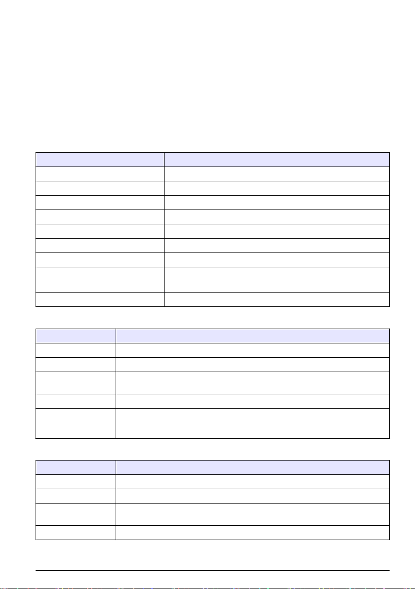
Table of contents
Specifications on page 3 Maintenance on page 16
General information on page 4 Troubleshooting on page 16
Installation on page 8 Replacement parts and accessories on page 16
Operation on page 16
Specifications
Specifications are subject to change without notice.
Table 1 General specifications
Specification Details
Operating temperature –10 to 50 °C (14 to 122 °F)
Storage temperature –5 to 40 °C (23 to 104 °F)
Relative humidity 20 to 80%, non-condensing
Altitude 2000 m (6562 ft) maximum
Overvoltage category 2
Pollution degree 2
Power requirements 24 VAC, 110–240 VAC, 50–60 Hz, 10 VA
CE compliance EN61326-1: EMC Directive
EN61010-1: LVD Directive
Warranty 1 year (EU: 2 years)
Table 2 Specifications—Air or water electrode cleaning system
Specification Details
Dimensions (W x H x D) 55 x 100 x 40 mm (9.8 x 13.8 x 5.9 in.)
Weight Approximately 0.4 kg (9.9 lbs)
Cleaning system Pressure: 0.5 to 10 bars (7.25 to 145 psi); temperature 70 °C (158 °F) maximum; flow:
400 to 4000 L/h
Environmental rating IP 65
Materials Enclosure material: Brass (MS); seal material: Fluoroelastomer (FKM), etylene
propylene diene monomer rubber (EPDM) and nitrile rubber (NBR); tubing:
Polyethylene (PE)
Table 3 Specifications—Chemical electrode cleaning system
Specification Details
Dimensions (W x H x D) 250 x 350 x 150 mm (9.8 x 13.8 x 5.9 in.)
Weight Approximately 4.5 kg (9.9 lbs)
Cleaning system Chemical reagent: air supply pressure 4 to 8 bar (58 to 116 psi); volume of reagent
supplied in each cycle: ± 10 mL
Suction height 2 m (6.5 ft) maximum
English 3

Table 3 Specifications—Chemical electrode cleaning system (continued)
Specification Details
Environmental rating IP 65
Materials Body material: Glass fiber and reinforced polyester; tubing: Polyvinyl chloride (PVC)
and PE
General information
In no event will the manufacturer be liable for direct, indirect, special, incidental or consequential
damages resulting from any defect or omission in this manual. The manufacturer reserves the right to
make changes in this manual and the products it describes at any time, without notice or obligation.
Revised editions are found on the manufacturer’s website.
Safety information
N O T I C E
The manufacturer is not responsible for any damages due to misapplication or misuse of this product including,
without limitation, direct, incidental and consequential damages, and disclaims such damages to the full extent
permitted under applicable law. The user is solely responsible to identify critical application risks and install
appropriate mechanisms to protect processes during a possible equipment malfunction.
Please read this entire manual before unpacking, setting up or operating this equipment. Pay
attention to all danger and caution statements. Failure to do so could result in serious injury to the
operator or damage to the equipment.
Make sure that the protection provided by this equipment is not impaired. Do not use or install this
equipment in any manner other than that specified in this manual.
Use of hazard information
D A N G E R
Indicates a potentially or imminently hazardous situation which, if not avoided, will result in death or serious injury.
WARNING
Indicates a potentially or imminently hazardous situation which, if not avoided, could result in death or serious
injury.
CAUTION
Indicates a potentially hazardous situation that may result in minor or moderate injury.
N O T I C E
Indicates a situation which, if not avoided, may cause damage to the instrument. Information that requires special
emphasis.
Precautionary labels
Read all labels and tags attached to the instrument. Personal injury or damage to the instrument
could occur if not observed. A symbol on the instrument is referenced in the manual with a
precautionary statement.
This is the safety alert symbol. Obey all safety messages that follow this symbol to avoid potential
injury. If on the instrument, refer to the instruction manual for operation or safety information.
This symbol indicates that a risk of electrical shock and/or electrocution exists.
4 English

This symbol indicates that the marked item can be hot and should not be touched without care.
This symbol identifies the presence of a strong corrosive or other hazardous substance and a risk of
chemical harm. Only individuals qualified and trained to work with chemicals should handle chemicals
or perform maintenance on chemical delivery systems associated with the equipment.
This symbol indicates the need for protective eye wear.
This symbol indicates the need for protective hand wear.
This symbol indicates that the marked item requires a protective earth connection. If the instrument is
not supplied with a ground plug on a cord, make the protective earth connection to the protective
conductor terminal.
Electrical equipment marked with this symbol may not be disposed of in European domestic or public
disposal systems. Return old or end-of-life equipment to the manufacturer for disposal at no charge to
the user.
Product overview
The POLYMETRON model 8544 is a cleaning system for electrodes. There are two models:
•Air or water electrode cleaning system: Models 8544.1 (220 V), 8544.2 (110 V) and
8544.3 (24 V). An electrovalve supplies air or water to the sensor tip. Refer to Figure 1.
•Chemical electrode cleaning system: Models 8544.4 (220 V), 8544.5 (110 V) and 8544.6 (24 V).
A twin chamber hose pump uses an air–instrument to supply a measured volume of a cleaning
fluid with a nozzle that is installed immediately below the sensor tip. Refer to Figure 2.
The manufacturer recommends that a junction box is used to connect the POLYMETRON
9500 series or SC200 controller to the system as shown in Figure 1 and Figure 2. Then, the cleaning
interval is configured at the controller. Refer to Replacement parts and accessories on page 16 for
ordering information.
English 5

Figure 1 Air or water electrode cleaning system
1 Junction box (optional) 4 Air or water inlet 7 Nozzle for 8340/44 probes
2 Controller (optional) 5 Cleaning module (electrovalve) 8 Nozzle for 8350 probes
3 Electrovalve connector 6 Brass adapter, air or water outlet
6 English
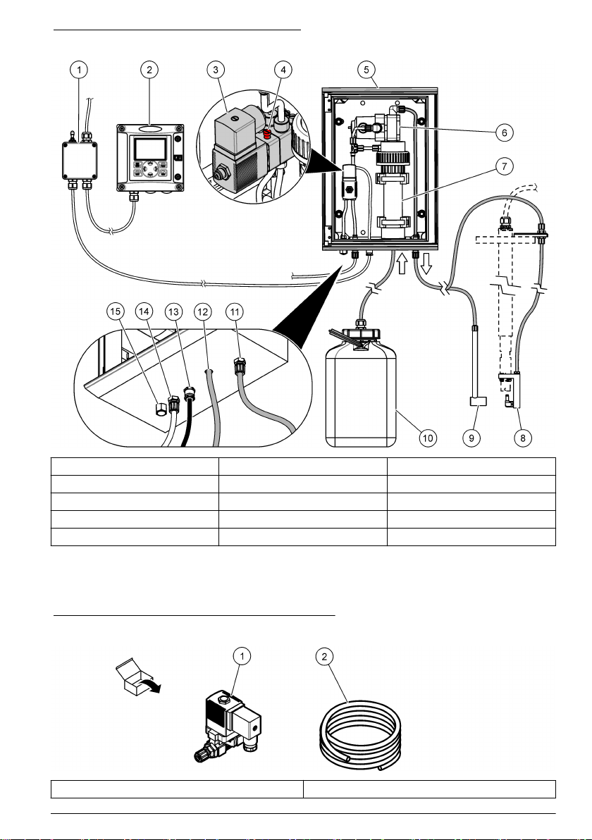
Figure 2 Chemical electrode cleaning system
1 Junction box (optional) 6 Valve 11 Cleaning solution outlet line
2 Controller (optional) 7 Hose pump 12 Cleaning solution intlet line
3 Electrovalve 8 Nozzle for 8350 probes 13 Power line
4 Manual starting button 9 Nozzle for 8340/44 probes 14 Air inlet
5 Cleaning module 10 Cleaning solution container 15 Purge and silencer
Product components
Make sure that all components have been received. Refer to Figure 3 and Figure 4. If any items are
missing or damaged, contact the manufacturer or a sales representative immediately.
Figure 3 Product components—Air or water system
1 Cleaning module 2 Tubing
English 7

Figure 4 Product components—Chemical system
1 Cleaning module 2 Enclosure key 3 Tubing
Installation
WARNING
Multiple hazards. Only qualified personnel must conduct the tasks described in this section of the
document.
Installation guidelines
N O T I C E
Make sure to install the instrument vertically. Make sure that the distance between the instruments and the
cleaning container is less than 2 m (6.6 ft).
Make sure that hazardous fluids or fluids that can produce hazardous vapors are handled safely.
These fluids must be handled in accordance with local regulatory agency requirements on
permissible exposure limits.
Install the instrument:
• In a location with a flat surface to prevent the unit from movement
• In a location with minimum mechanical vibrations and electronic noise
• In a location where the power switch and power cord are visible and easily accessible
• In a location where there is sufficient clearance around it to make plumbing and electrical
connections
Keep the sample tubing as short as possible to minimize lag time. Keep the instrument away from a
heat source.
8 English

Electrical installation
D A N G E R
Electrocution hazard. Always remove power to the instrument before making electrical connections.
Wiring for power
D A N G E R
Electrocution hazard. Protective Earth Ground (PE) connection is required.
D A N G E R
Electrical shock and fire hazards. Make sure to identify the local disconnect clearly for the conduit
installation.
WARNING
Potential Electrocution Hazard. If this equipment is used outdoors or in potentially wet locations, a
Ground Fault Interrupt device must be used for connecting the equipment to its mains power source.
WARNING
Electrical shock and fire hazards. Make sure that the user-supplied power cord and non‐locking plug
meet the applicable country code requirements.
N O T I C E
Install the device in a location and position that gives easy access to the disconnect device and its operation.
Supply power to the instrument with conduit or a power cable. Make sure that a circuit breaker with
sufficient current capacity is installed in the power line. The circuit breaker size is based on the wire
gauge used for installation.
For installation with conduit:
• Install a local disconnect for the instrument within 3 m (10 ft) of the instrument. Put a label on the
disconnect that identifies it as the main disconnect device for the instrument.
• Make sure that the power and safety ground service drops for the instrument are 18–12 AWG and
the wire insulation is rated for 300 VAC or higher.
• Connect equipment in accordance with local, state or national electrical codes.
• Connect the conduit through a conduit hub that holds the conduit securely and seals the enclosure
when tightened.
• If metal conduit is used, make sure that the conduit hub is tightened so that the conduit hub
connects the metal conduit to safely ground.
For installation with a power cable, make sure that the power cable is:
• Less than 3 m (10 ft) in length
• Rated sufficient for the supply voltage and current. Refer to the requirements in Specifications
on page 3.
• Rated for at least 60 °C (140 °F) and applicable to the installation environment
• Not less than 18 AWG with applicable insulation colors for local code requirements
• A power cable with a three-prong plug (with ground connection) that is applicable to the supply
connection
English 9

• Connected through a cable gland (strain relief) that holds the power cable securely and seals the
enclosure when tightened
• Does not have a locking type device on the plug
Connect conduit or a power cord
Connect the instrument to power with conduit or a power cord. Refer to Wiring for power on page 9.
Make connections at the same terminals, regardless of the type of wire used. Put each wire into the
applicable terminal until the insulation is flush against the connector with no bare wire seen. Pull
lightly after insertion to make sure that there is a tight connection.
Connect air or water system
Connect the instrument to power with conduit or a power cord. Refer to Wiring for power on page 9.
Make connections at the same terminals, regardless of the type of wire used. Put each wire into the
applicable terminal until the insulation is flush against the connector with no bare wire seen. Pull
lightly after insertion to make sure that there is a tight connection.
1. Complete the steps shown in Figure 5.
2. Connect the live (L), neutral (N), and ground (G) wires to the electrovalve connector as shown in
Figure 6 and Table 4.
Figure 5 Electrical wiring connection—Air or water system
10 English
Tabla de contenidos
Idiomas:
Otros manuales de Bomba de agua de Hach

Manuales populares de Bomba de agua de otras marcas


Sykes AmeriPumps
Sykes AmeriPumps GP100M Guía de solución de problemas

DUROMAX
DUROMAX XP WX Series Manual de usuario

BRINKMANN PUMPS
BRINKMANN PUMPS SBF550 Manual de usuario

Franklin Electric
Franklin Electric IPS Manual de usuario

Xylem
Xylem e-1532 Series Manual de usuario

Milton Roy
Milton Roy PRIMEROYAL Manual de usuario