Grundfos AMG Instrucciones de funcionamiento

AMG
50/60 Hz
Service instructions
AMG 50/60 Hz
Installation and operating instructions
Other languages
http://net.grundfos.com/qr/i/97908898
GRUNDFOS INSTRUCTIONS


English (US) Service instructions
Original service instructions
Table of contents
1. General information ........................4
1.1 Hazard statements..........................4
1.2 Notes ..................................4
1.3 Safety .................................5
2. Preparing the dismantling of the product ..........5
2.1 Transporting the product ......................5
2.2 Contaminated products .......................5
2.3 Handling and storing the product .................5
3. Dismantling and assembling the product ..........6
3.1 Explosion-proof versions ......................6
3.2 ......................................6
3.3 Dismantling the product.......................6
3.4 Assembling the product .......................8
4. Additional information .....................11
4.1 Oil types and quantity .......................11
4.2 Special tools ............................11
4.3 Torques and lubricants ......................12
4.4 Sectional drawings.........................14
5. Document quality feedback ..................21
1. General information
Read this document before you install the product.
Installation and operation must comply with local
regulations and accepted codes of good practice.
1.1 Hazard statements
The symbols and hazard statements below may appear in Grundfos
installation and operating instructions, safety instructions and
service instructions.
DANGER
Indicates a hazardous situation which, if not avoided, will
result in death or serious personal injury.
WARNING
Indicates a hazardous situation which, if not avoided,
could result in death or serious personal injury.
CAUTION
Indicates a hazardous situation which, if not avoided,
could result in minor or moderate personal injury.
The hazard statements are structured in the following way:
SIGNAL WORD
Description of the hazard
Consequence of ignoring the warning
• Action to avoid the hazard.
1.2 Notes
The symbols and notes below may appear in Grundfos installation
and operating instructions, safety instructions and service
instructions.
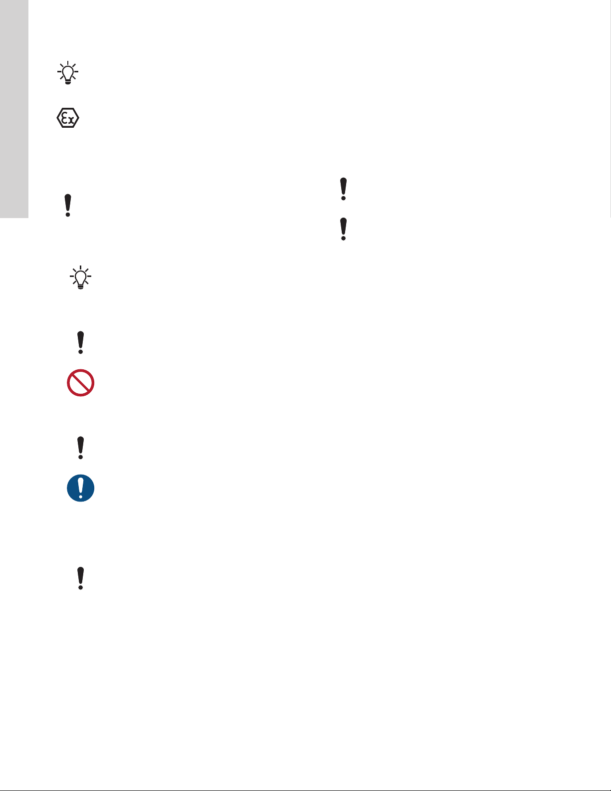
Observe these instructions for explosion-proof products.
A blue or grey circle with a white graphical symbol
indicates that an action must be taken.
A red or grey circle with a diagonal bar, possibly with a
black graphical symbol, indicates that an action must not
be taken or must be stopped.
If these instructions are not observed, it may result in
malfunction or damage to the equipment.
Tips and advice that make the work easier.
4
English (US)

1.3 Safety
Installation of products in pits must be carried out by
specially trained persons.
Work in or near pits must be carried out according to local
regulations.
DANGER
‐It must be possible to lock the main switch in position
0. Type and requirements as specified in local
regulations.
Persons must not enter the installation area when the
atmosphere is explosive.
For safety reasons, all work in pits must be supervised by a person
outside the pit.
We recommend that you carry out all maintenance and
service work when the product is placed outside the pit.
Pits for submerged sewage and wastewater products may contain
sewage or wastewater with toxic and/or disease-causing
substances. Therefore all persons involved must wear appropriate
personal protective equipment and clothing, and all work on and
near the product must be carried out under strict observance of
hygienic regulations in force.
DANGER
Crushing hazard
‐Always lift the product by its lifting bracket or by
means of a forklift truck if the product is on a pallet. Do
not lift the product by the power cable.
2. Preparing the dismantling of the product
2.1 Transporting the product
Transport the product in horizontal position. Make sure the product
cannot roll of fall over.
See the installation and operating instructions for mixers, type AMG
(96498078). Use the QR code and the link on the front of this
document.
2.2 Contaminated products
See the installation and operating instructions for mixers, type AMG
(96498078). Use the QR code and the link on the front of this
document.
2.3 Handling and storing the product
2.3.1 Handling the product
The product weights between 78 and 280 kg with motor bracket and
10 m cable. It is therefore important to use the correct lifting
equipment. The product weight is stated on the nameplate.
Make sure that all lifting equipment is rated for the
purpose.
Check the lifting equipment for damage before attempting
to lift the components.
DANGER
Crushing hazard
‐Always lift the product by its lifting bracket or by
means of a forklift truck if the product is on a pallet. Do
not lift the product by the power cable.
Do not lift the product by the power cable. It may result in
electric short circuit and risk of shock when the product is
connected to the mains. The cable and cable entry my be
damaged, leading to loss of watertightness and
consequent severe damage to the motor.
2.3.2 Storing the product
See the installation and operating instructions for mixers, type AMG
(96498078). Use the QR code and the link on the front of this
document.
5
English (US)

3. Dismantling and assembling the product
WARNING
‐Before starting any service work, remove the fuses or
switch off the power supply. Make sure that the power
supply cannot be accidentally switched on.
‐Disconnect the power cable in accordance with local
regulations.
WARNING
Rotating blades
‐Before starting any work, make sure the blades have
stopped rotating.
CAUTION
Falling
‐Make sure that persons cannot accidentally fall into
the pit, for example by installing a cover or railing.
All regulations applying to products installed in potentially
explosive environments must be observed.
Make sure that no work is carried out in potentially
explosive environment.
Before starting any work on the products used in liquids, which
could constitute a hazard to health, thorough cleaning or venting of
the product, pit, etc. must be carried out according to local
regulations.
3.1 Explosion-proof versions
Explosion-proof versions must be serviced and repaired by
Grundfos or by an authorised service partner by Grundfos.
Spare parts
Damaged parts must always be replaced by new approved parts.
Motor parts must not be reconditioned by machining, retapping,
welding, etc.
3.2
Position numbers of parts (digits) refer to section Oil types and
quantity.
Before dismantling
• Check the generation of the product.
• Switch off the power supply.
• Disconnect the power cable in accordance with local
regulations.
Before assembly
• Clean and check all parts.
• Replace defective parts by new parts.
• Order the necessary service kits.
• Always replace gaskets and O-rings.
During assembly
• Lubricate and tighten screws and nuts according to section
Torques and lubricants.
Related information
4.3 Torques and lubricants
3.3 Dismantling the product
Position numbers of parts (numbers in brackets refer to
section Standard products.
Position numbers of tools (letters in brackets) refer to
section Special tools.
Maintenance and service work on explosion-proof
products must be carried out by Grundfos or a service
workshop authorised by Grundfos.
Related information
4.2 Special tools
3.3.1 Removing the propeller
1. Remove the upper plug (1102).
2. Remove the plug (1101) and drain the oil into a suitable
container.
3. Remove the screw (1111), washer (1110), hub cover (1109) and
O-ring (1108).
4. Unlock the lock washer (1107) from the slotted nut (1106). Note:
This applies only to old versions. See Explosion-proof versions.
5. Remove the outer slotted nut (1106) with a suitable tool.
6. Remove the lock washers (1107).
7. Remove the inner slotted nut (1106).
8. Gently tap on the back of the propeller with a plastic hammer to
remove it from the shaft.
Related information
3.1 Explosion-proof versions
3.3.2 Sealing system of propeller hub and gear casing
1. Remove the hub lip seals (1104) from the inside of the hub.
2. Remove the key (1105) from the shaft.
3. Remove the sleeve (1096) from the wear ring (1097).
Make sure not to damage the surface of the wearing
ring.
4. Remove the rotating shaft seal part (1098) from the gear shaft
(1093).
5. Gently tap on the side of the wear ring to remove it from the
gear casing.
6. Remove the stationary shaft seal part (1098) from the wear ring.
7. Remove the intermediate ring (1095) from the wear ring.
6
English (US)

3.3.3 Removing the gear casing
1. Cut with a knife between the motor flange (1020) and the gear
housing (1088) to protect the paint.
2. Remove the screws (1099). Lift the unit with a crane and knock
the motor housing free of the gear casing. Remove the gear
casing.
3. Remove the planet carrier (1067) and the sun wheel (1060).
4. Remove the O-ring (1071) from the sun wheel.
5. Remove the O-ring (1022) from the motor flange (1020).
6. Remove the lower lip seal (1054) from the motor flange. Note:
This applies only to non-explosion-proof mixers.
Explosion-proof mixers have a mechanical shaft seal
instead of a lip seal.
7. Remove the screws (1064) from the ring gear (1062).
8. Remove the ring gear.
9. Remove the retaining ring (1089) from the gear shaft (1093).
10. Unlock the lock washer (1091) from the slotted nut (1090).
11. Remove the slotted nut and the lock washer from the shaft.
12. Knock the shaft out of the gear casing using a plastic hammer.
The inner bearing ring (1092) is removed at the same time.
13. Remove both outer bearing rings (1092 and 1094).
14. Remove the inner bearing ring (1094) from the shaft.
3.3.4 Draining the oil
1. Place the motor in vertical position with the shaft upwards.
Remove the plug (1052) and drain the oil into a suitable
container. Note: This applies only to non-explosion-proof
mixers.
Explosion-proof mixers do not have any oil inside the
motor.
3.3.5 Removing the cable
1. Place the motor in horizontal position with the terminal box
upwards.
2. Remove the screws (1024).
3. Cut with a knife along the terminal box cover (1023) to protect
the paint.
4. Remove the terminal box cover and the O-ring (1025).
5. Write down the numbers on the wires to ensure correct
connection.
6. Disconnect the cable conductors from the motor windings
including the screw (1028).
7. Remove the cable relief (1009) from the cable (1001).
8. Cut with a knife between the terminal box and the cable flange
(1002) to protect the paint.
9. Remove the screws (1008), cable flange (1002) and cable
(1001).
10. Remove the small cable seal (1006), thrust washer (1005), large
cable seal (1004), cable guide (1003) and cable flange (1002)
with O-ring (1007).
3.3.6 Removing the motor
1. Place the motor in vertical position with the shaft upwards.
2. Remove the gear head. See section Removing the gear casing.
3. Remove the screws (1021).
4. Cut with a knife between the motor flange (1020) and the motor
housing (1017) to protect the paint.
5. Screw two screws into the threaded holes of the motor flange to
separate the motor flange and the motor housing.
6. Remove the motor flange from the motor housing.
Make sure not to damage the wires of the water-in-oil
sensor (1049).
7. Remove the water-in-oil sensor (1049).
8. Remove the seal washer (1173) from the water-in-oil sensor.
9. Place the motor in horizontal position.
10. Remove the compensation disc (1038) from the ND-end of the
motor housing.
11. Remove the bearing (1039) from the rotor shaft (1019).
12. Place the motor flange and the rotor in a hydraulic press and
separate them using a special pin tool.
13. Remove the bearing (1047) from the rotor shaft.
14. Remove the upper lip seal (1055) from the rotor shaft. Note:
This applies only to non-explosion-proof mixers.
Explosion-proof mixers have a mechanical shaft seal
instead of a lip seal.
15. Remove the O-ring (1022) from the motor flange.
Related information
3.3.3 Removing the gear casing
3.3.7 Removing the stator
AMG.20-55 [ANSI] and AMG.15-40 [DIN]
1. Remove the nut (1158), spring washer (1045) and screw (1044)
from the terminal box inside the motor housing (1017) and mark
the position of the stator.
2. Remove the stator (1018) from the motor housing (1017).
Make sure not to damage any wires.
AMG.75-250 [ANSI] and AMG.55-180 [DIN]
1. Remove the nut (1146), spring washer (1056) and screw (1044)
from the terminal box outside the motor housing.
2. Remove the stator (1018) from the motor housing (1017).
Make sure not to damage any wires.
3. Remove the nut (1046) from the motor housing (1017).
4. Remove the screw (1044) from the motor housing (1017).
5. Disconnect the stator wires from the motor housing (1017) and
pull the stator (1018) out of the motor housing.
7
English (US)

3.4 Assembling the product
Position numbers of parts (numbers in brackets refer to
section Standard products.
Position numbers of tools (letters in brackets) refer to
section Special tools.
Maintenance and service work on explosion-proof
products must be carried out by Grundfos or a service
workshop authorised by Grundfos.
Related information
4.2 Special tools
3.4.1 Fitting the stator and motor
Lubricate and tighten the screws and nuts according to
section Torques and lubricants.
1. Insert the bearing (1047) into the motor flange (1020) and fit the
upper lip seal (1055) with the opening pointing away from the
bearing.
Explosion-proof mixers have mechanical shaft seal
instead of lip seal.
2. Press the rotor (1019) into the motor flange (1020). Make sure
the motor flange (1020) rotates freely.
Make sure that the rotor is positioned correctly.
Do not use a hammer.
3. Heat the bearing (1039) and fit it on the ND-end of the rotor
shaft.
If a bearing heater is used, the temperature must not
exceed 176 °F (80 °C).
Use a hydraulic press if a bearing heater is not
available.
4. Fit the seal washer (1173) on the water-in-oil sensor (1049) and
lubricate the washer and threads.
5. Fit the water-in-oil sensor (1049) in the motor flange (1020) and
tighten gently.
Keep the wires of the water-in-oil sensor away from
the bearing, for instance by means of a plastic strip.
6. Lubricate the groove for the O-ring (1022) on the motor side of
the motor flange.
7. Fit and lubricate the O-ring (1022).
8. Place the rotor with the motor flange upwards
9. Fit the lower lip seal (1054) with the opening upwards (pointing
away from the bearing). Tap gently, if needed.
10. Lubricate the groove for the O-ring (1022) on the gear side of
the motor flange (1020).
11. Fit and lubricate the O-ring (1022).
12. Insert the stator (1018) in the motor housing (1017).
Make sure that the fixation holes for alignment are
positioned correctly.
Make sure not to damage any wires.
AMG.20-55 [ANSI] and AMG.15-40 [DIN]
1. Fit the screw (1044) in the motor housing (1017) and tighten
gently.
2. Fit the spring washer (1045) and the nut (1158).
3. Tighten the nut (1158).
AMG.75-250 [ANSI] and AMG.55-185 [DIN]
1. Fit the screw (1044), seal washer (1056) and nut (1046).
All types
1. Lead the wires into the terminal box.
2. Place the motor housing (1017) in vertical position.
3. Fit the compensation disc (1038) in the ND-end of the motor
housing (1017).
4. Insert the rotor in the motor housing (1017). Lead the wires of
the water-in-oil sensor (1049) to the junction box before the
rotor is fully inserted.
5. Align the motor flange with the water-in-oil sensor pointing away
from the terminal box.
6. Fit and tighten the screws (1021) a little by hand.
Related information
4.3 Torques and lubricants
8
English (US)

3.4.2 Fitting the cable
1. Place the motor in horizontal position.
2. Fit the cable flange (1002) and the O-ring (1007) on the cable
(1001).
3. Fit the O-ring (1007) in the cable flange (1002).
4. Lubricate the surface of the cable (1001).
5. Fit the cable guide (1003), large cable seal (1004), thrust
washer (1005) and small cable seal (1006) on the cable (1001).
6. Lubricate the complete seal unit.
7. Fit the seal unit in the terminal box and at the same time pull the
wires gently in the terminal box.
8. Lubricate the threads of the screws (1008).
9. Fit and tighten slightly the screws (1008) in the cable flange
(1002).
10. Fit and fasten the cable relief (1009) on the cable.
Make sure that you have enough cable in the terminal
box before tightening the cable relief.
11. Tighten the screws (1008).
12. Fit the screw (1028) and the lock washer (1029).
13. Connect the wires according to the notes you made during
dismantling. Secure the connections with terminal tubes and
shrink-on sleeves.
14. Fill the motor with oil. See section Filling the oil. Note: The
section applies only to non-explosion-proof products.
15. Press the wires gently in the terminal box.
16. Lubricate the groove in the terminal box cover (1023).
17. Fit and lubricate the O-ring (1025).
18. Fit the terminal box cover (1023) to the terminal box.
19. Lubricate the threads of the screws (1024).
20. Fit and tighten the screws (1024).
Related information
3.4.3 Filling the oil
Explosion-proof mixers do not have any oil inside the
motor.
1. Remove the screw (1041) and the U-washer (1040) from the
motor housing (1017).
2. Wrap PFTE tape around the plug (1052). Fit and tighten the
plug in the motor housing (1017).
3. Fill the motor with oil through the hole in the terminal box. See
section Oil types and quantity.
4. Lubricate the screw (1041) and fit the U-washer (1040) on the
screw.
5. Fit and tighten the screw (1041) in the motor housing (1017).
Related information
4.1 Oil types and quantity
3.4.4 Fitting the gear casing
Lubricate and tighten the screws and nuts according to
section Torques and lubricants.
1. Fit the ring gear (1062) in the gear casing (1088).
2. Lubricate the threads of the screws (1064).
3. Fit and tighten the screws (1064).
4. Fit the outer ring of bearing (1092) in the gear casing (1088) by
tapping gently (C).
5. Fit the outer ring of bearing (1094) in the gear casing (1088) by
tapping gently (C).
6. Heat the roller part of bearing (1094) using a bearing heater and
fit it on the shaft.
If a bearing heater is used, the temperature must not
exceed 176 °F (80 °C).
Use a hydraulic press if a bearing heater is not
available.
7. Fit the shaft (1093) in the gear casing (1088).
8. Heat the bearing (1092) using a bearing heater and fit it on the
shaft (C) by tapping gently, if needed.
9. Fit the lock washer (1091) and the slotted nut (1090) on the
shaft. Tighten the slotted nut (B).
10. Fit the retaining ring (1089) on the shaft.
11. Wrap PFTE tape around the plug (1101).
12. Fit and tighten the plug (1101) in the seal housing (1088).
13. Fit the O-ring (1071) in the sun wheel (1060).
14. Lubricate the O-ring (1071) and fit it on the shaft.
Make sure that the lower lip seal (1054) is intact, and
check that the motor shaft can rotate freely.
Explosion-proof mixers do not have lip seal.
15. Lubricate the retaining ring (1089) side that faces the sun wheel
(1060).
16. Fit the sun wheel (1060) on the shaft.
17. Fit the planet carrier (1067).
18. Fit the gear casing (1088) on the motor flange.
19. Lubricate the threads of the screws (1099).
20. Fit and fasten the gear casing (1088) with screws (1099) on the
motor flange.
21. Apply a new coat of paint if the coat is damaged.
Related information
4.3 Torques and lubricants
9
English (US)

3.4.5 Fitting the sealing system of propeller hub and gear
casing
Lubricate and tighten the screws and nuts according to
section Torques and lubricants.
1. Lubricate the wear ring (1097) and place it in the propeller end
of the gear casing (1088). Press home with special tool (D).
2. Insert the intermediate ring (1095) in the wear ring (1097) if the
version requires an additional ring.
3. Lubricate the outer surface of the stationary part of the shaft
seal (1098) and inner surface of the wear ring (1097).
4. Fit the stationary part (1098) in the wear ring (1097) and press it
home with a special tool (D). Tap gently, if needed.
5. Remove the lubricant and clean the surface of the stationary
part of the shaft seal (1098).
6. Remove the inner ring from the rotating part of the shaft seal
(1098).
7. Lubricate the inner surface of the shaft seal (1098).
8. Fit the rotating part of the shaft seal (1098) on the shaft and
press it home (C).
9. Lubricate the first lip seal (1004) and the inner part of the hub.
10. Fit the first lip seal (1104) in the hub with special tool (F) by
tapping. Place the lip seal with the open side pointing away from
the hub.
11. Lubricate the outer part of the first lip seal (1044).
12. Fit the second lip seal (1104) as described in step 10.
13. Lubricate the inner surfaces of the lip seals (1104).
14. Fill the gear with oil. See section Standard products.
15. Fit the key (1105) in the gear shaft (1093) by gently tapping, if
needed.
16. Lubricate the gear shaft (1093) and fit the hub with the
premounted lip seals on the gear shaft.
17. Fit and tighten (A) the slotted nut (1106) on the shaft with the
chamfered end pointing away from the hub.
18. Bend one tab down from the lower lock washer (1107).
19. Fit the lock washer (1107) with the bent tab on the shaft (back to
back) so that the bent tab will fit in the groove of the slotted nut
(1106).
20. Fit the second lock washer (1107).
21. Fit and tighten (A) the second slotted nut (1106) on the shaft
with the chamfered end towards the hub.
22. Lock the second slotted nut (1106) with the lock washers (1107)
by bending one tab so that it fits to the groove in the nut (1106).
23. Fill the hub top partly with gear oil. See section Oil types and
quantity.
24. Fit the O-ring (1108) to the hub.
25. Fit the hub cover (1109).
26. Lubricate the thread of the screw (1111) and the washer (1110).
27. Fit and tighten the washer (1110) and the screw (1111).
28. Wrap PFTE tape around the plug (1101).
29. Fit and tighten the plug (1101) in the gear casing (1088).
30. Fill the gear casing (1088) with oil through the hole for the plug
(1102). See section Oil types and quantity.
31. Wrap PFTE tape around the plug (1102).
32. Fit and tighten the plug (1102) in the gear casing (1088).
33. Apply a new coat of paint if the coat is damaged.
Related information
4.1 Oil types and quantity
4.3 Torques and lubricants
10
English (US)
Tabla de contenidos