Groupe Atlantic NAVISTEM B2000 Manual de usuario

CONTROL PANEL FOR
CLASSIC BOILERS
NAVISTEM B2000
MANUFACTURER:
SITE DE CAUROIR
C
O
L
L
E
C
T
I
V
E
P
R
O
D
U
C
T
Route de Solesmes
FR - 59400 CAUROIR
Instructions
for installation,
use and
maintenance
Document No. 0TA0Z0110-C / 01.02.2018
FR EN DE ES IT NL

Page 2 / 76 0TA0Z0110-C
NAVISTEM B2000 - Installation, use and maintenance

CONTENTS
1. WARNINGS AND COMPLIANCE ....................................................................................... 4
2. TECHNICAL SPECIFICATIONS ......................................................................................... 6
2.1. General ......................................................................................................................................................... 6
2.2. Dimensions ................................................................................................................................................... 6
2.3. Delivered unit ................................................................................................................................................ 6
2.4. Technical data ............................................................................................................................................... 7
2.5. Thermostat module ....................................................................................................................................... 8
2.6. Basic control panel equipment ...................................................................................................................... 9
2.7. Regulation/Regulator .................................................................................................................................. 10
3. INSTALLATION .................................................................................................................. 12
3.1. Installation of the control panel ................................................................................................................... 12
3.2.Fittingsensors(bulbsorowsensors)........................................................................................................ 13
3.3. Electrical connection ................................................................................................................................... 16
4. ADDITIONAL ACCESSORIES.......................................................................................... 24
4.1. Temperature sensors .................................................................................................................................. 24
4.2. Remote control QAA75 ............................................................................................................................... 25
4.3. Other accessories ....................................................................................................................................... 26
5. USING THE CONTROL PANEL........................................................................................ 27
5.1.Start-up(Commissioning) ........................................................................................................................... 27
5.2.Breakdownmaintenance............................................................................................................................. 28
6. HYDRAULIC DIAGRAMS AND CONFIGURATIONS ..................................................... 31
6.1. Symbols used in the diagrams .................................................................................................................... 31
6.2. List of diagrams........................................................................................................................................... 31
7. SPARE PARTS LIST.......................................................................................................... 72
Edition: 02 / 2018 Page 3 / 76
NAVISTEM B2000 - Installation, use and maintenance

1. WARNINGS AND COMPLIANCE
Unpacking and reservations
With the carrier present, carefully check the general appearance of the packaging and
of the control panel. If in doubt, do not use the appliance.
Inthecaseofanydispute,stateanyappropriatereservationstothecarrierinwriting
within48hoursandsendacopyofthislettertotheAfter-Salesservice.
Storage
The control panel:
• mustbearrangedhorizontallyinaplacewherethetemperatureisbetween0°C
and+50°C
• must be protected from humidity.
Symbols used in this document
INFORMATION: Thissymboldrawsattentiontocomments.
!WARNING: Failure to comply with these instructions may cause damage to the
installation or to other objects.
!
DANGER: Failure to comply with these instructions may cause injury and serious
material damage.
DANGER: Failuretocomplywiththeseinstructionsmaycauseelectrocution.
Compliance with European Directives
Low voltage (2006/95/CE)
• ThisappliancecomplieswithallrequirementsoflowvoltagedirectiveEN60730-
1 + EN60730-2-9.
• This appliance is not intended for use by persons (including children)
whose physical, sensory or mental abilities are reduced, or persons
without experience or knowledge, unless they have been able to
benet, through someone responsible for their safety, from supervision or prior
instruction concerning the use of the appliance.
• Childrenmustbesupervisedtoensuretheydonotplaywiththeappliance.
Page 4 / 76 0TA0Z0110-C
NAVISTEM B2000 - Installation, use and maintenance

Electromagnetic compatibility (2004/108/CEE)
• Thisapplianceconformswithallrequirementsoftheelectromagneticcompatibility
directive EN61000 - 6 - 1, EN61000 - 6 - 3.
• This is a class A appliance. In a residential environment, this appliance may cause
radio-electric interference. In this case, the user may be asked to take appropriate
measures.
Environmental compatibility
• This appliance contains electrical and electronic elements which must not be
thrownawaywithhouseholdwaste.
• Locallegislationmustbecompliedwith.
Installation and maintenance rules
The control panel must be installed and maintained by an approved professional in
accordancewiththeprevailingregulationsandcodeofpractice,inparticular:
• Complywithrulesinforceandwithspecicinstructionsandnormsapplicablein
the country of installation.
!
WARNING: Thecontrolpanelisclassiedasanappliancewhichisnotaccessibletothe
public(closedelectricaloperatingzone).
!
WARNING: The control panel must only be used for the purpose for which it was
designed; any other use must be considered inappropriate and therefore
dangerous.
!WARNING: Theappliancemustbeshelteredfromrain,snowandfrost.
!DANGER: Thecontrolpanelandtheheatregulatorsinsideitcannot beexposedto
temperatureshigherthan45°Cwheninoperation.
INFORMATION: Thisproductmustbeassembled,usedandmaintainedincompliancewith
the information provided in these technical instructions.
DANGER: Alwaysturnthecontrolpanelobeforecarryingoutanyworkonit.
!DANGER: Alwaysturnthecontrolpanelobeforecarryingoutanyworkontheburner,
boiler or other heating elements (pumps, valves, etc.) controlled by the
control panel.
Edition: 02 / 2018 Page 5 / 76
NAVISTEM B2000 - Installation, use and maintenance

2. TECHNICAL SPECIFICATIONS
2.1. General
The NAVISTEM B2000 control commands the boiler's burner and heating circuits
depending on the installation. All elements of the installation can thus be handled and
commanded easily from one place.
The control panel's capacities can be increased by adding accessories:
• AdditionalheatingregulatorRVS46(+displayAVS37)
2.2. Dimensions
gure 1 - Dimensions (in mm)
2.3. Delivered unit
• Sheet metal casing
• Thermostat module
• Heating regulator RVS63
• Boiler sensor
• Instructions for servicing, installation and technical guidelines
• Electrical diagram
• Instructions for regulator RVS63
• Assemblykit(screws)
540
438
147
172
Page 6 / 76 0TA0Z0110-C
NAVISTEM B2000 - Installation, use and maintenance

2.4. Technical data
Name of manufacturer YGNIS INDUSTRIE
Unique reference NAVISTEM B2000
Single-phase power supply 230 VAC 50Hz
Rated current 16 A
Casing protection index IP20
Reference operating
temperature T45
Degree of pollution Degree of pollution II
Protection index Class I
(surgevoltage=800V)
Safety thermostat 110°CMaximumTemperature
(+0/-9°C)
Burner thermostat setting at
speed 1 35…95°C(+/3°C).Tosettothe
maximumvalueof95°C
Burner thermostat setting at
speed 2 Inactive for a NAVISTEM
B2000 control panel
Electrical consumption Depends on appliances
plugged in (burners, pumps,
mixingvalves)
Maximum installation
altitude 2,000 m
Relative humidity 5 to 95%
Terminal output power Voltage: 230V AC (+10%/-
15%)
Amperage: 5 mA to 2 A.
GWFI plastic interface 550°C
Type of printed circuit
board(s) coating EPOXY FR4 FT glass
Other technical data See instructions for regulator
RVS63
!
WARNING: The control thermostat must be set to its maximum setting to avoid
interferencewiththeelectronicregulatorRVS63.
Edition: 02 / 2018 Page 7 / 76
NAVISTEM B2000 - Installation, use and maintenance
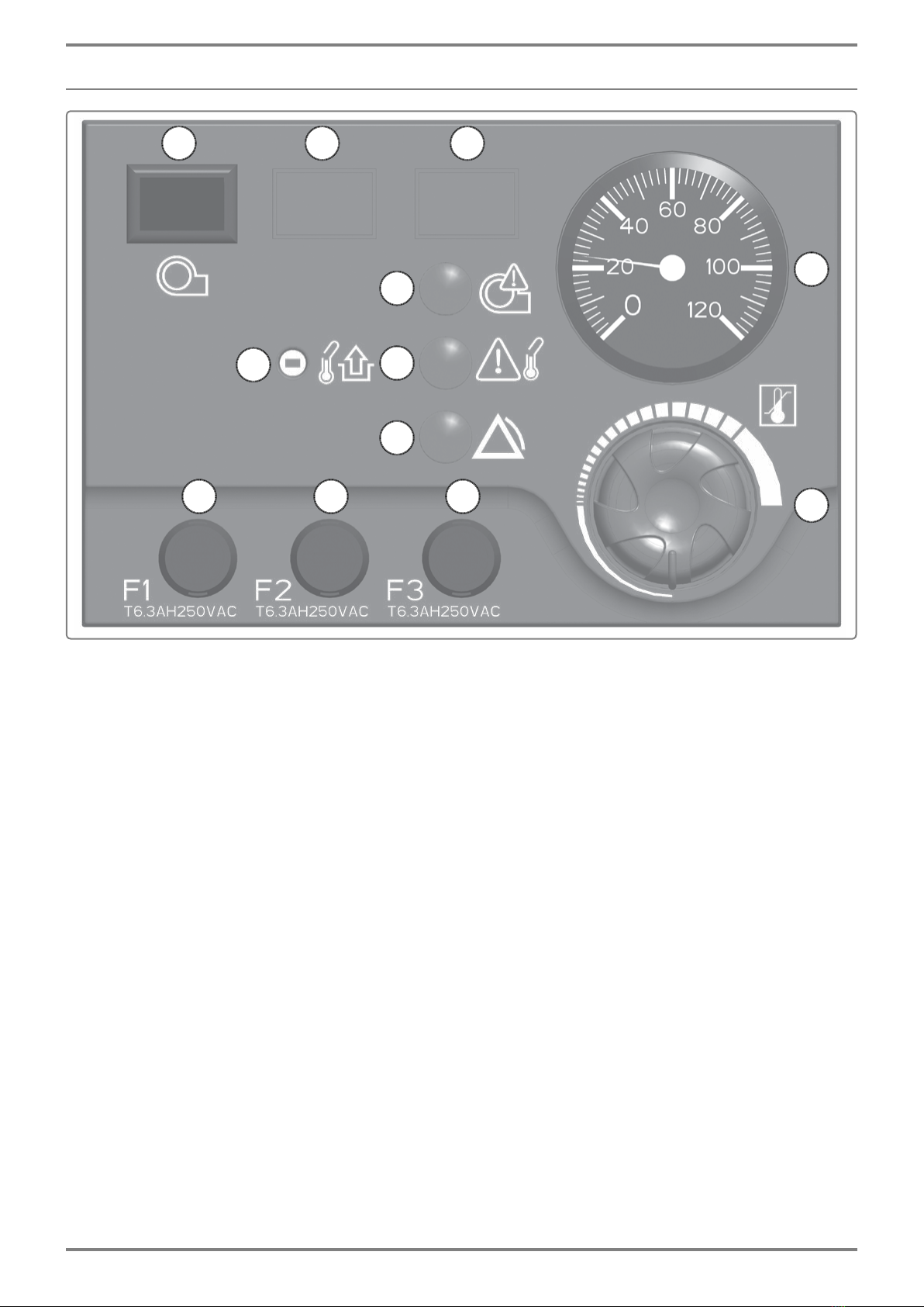
2.5. Thermostat module
gure 2 - Thermostat module
Legend
1: F1: 6.3 AH 250 V AC Burner / Boiler fuse
2: F2:6.3AH250VACHeatingregulatorfuse(RVS63)
3: F3:6.3AH250VACadditionalheatingregulatorfuse(soldasanaccessory)
4: Safetythermostat(resetbutton)
5: First speed and second speed control thermostat (inactive on a
NAVISTEMB2000controlpanel).
6: ON/OFFswitchforburnerpowersupply
7: Thermometer: indication of the boiler's temperature
8: LEDindicatingaproblemwiththesafetythermostat(boilertemperaturetoo
high)
9: LEDindicatinganexternalproblem
10: LEDindicatingaproblemwiththeburner
11: Positionfortheburner'sremoteresetbutton(optional)
12: PositionforTUVswitch(optional)
21
10
9
8
7
6
5
4
3
12 11
Page 8 / 76 0TA0Z0110-C
NAVISTEM B2000 - Installation, use and maintenance

2.6. Basic control panel equipment
1: Thermostat module
2: Connector for alarm relay board
3: AdditionalpowersupplyconnectorRVS46
4: Burner connection terminal
5: Connection terminal to release the burner's
operation
6: Powersupplyandconnectionterminalof
safety devices specific to the installation
7: Accessory terminal for three-phase burner
powersupply(notincludedwithcontrolpanel.
Tobeorderedasanaccessory).
gure 3 - Basic control panel equipment
1
4
2
3
5
6
7
Edition: 02 / 2018 Page 9 / 76
NAVISTEM B2000 - Installation, use and maintenance

2.7. Regulation/Regulator
gure 4 - Regulation/Regulator
1: DisplayAVS37(suppliedwithaccessoryRVS46)
2: DisplayAVS37(basicNAVISTEMB2000controlpanelequipment)
3: AdditionalregulatorsoldasaccessoryRVS46(withdisplay)
4: RegulatorRVS63(basicNAVISTEMB2000controlpanelequipment)
5: Regulationelectronicboard(basicNAVISTEMB2000controlpanelequipment)
2.7.1. Heating regulator RVS63 + display AVS37
Theregulatorallowsthefollowing:
• Commandofaone-speed,two-speedormodulatingburner
• Command of a direct heating circuit
• Command of two heating circuits or one heating circuit and one mixing valve
protectingtheheatexchangerreturntemperature
• Commandofdomestichotwaterpreparation
• Cascade with one or more other boilers tted with a SIEMENS regulator (LPB
communicationbus).
1 2
3
4 5
Page 10 / 76 0TA0Z0110-C
NAVISTEM B2000 - Installation, use and maintenance
Tabla de contenidos
Otros manuales de Panel de control de Groupe Atlantic


