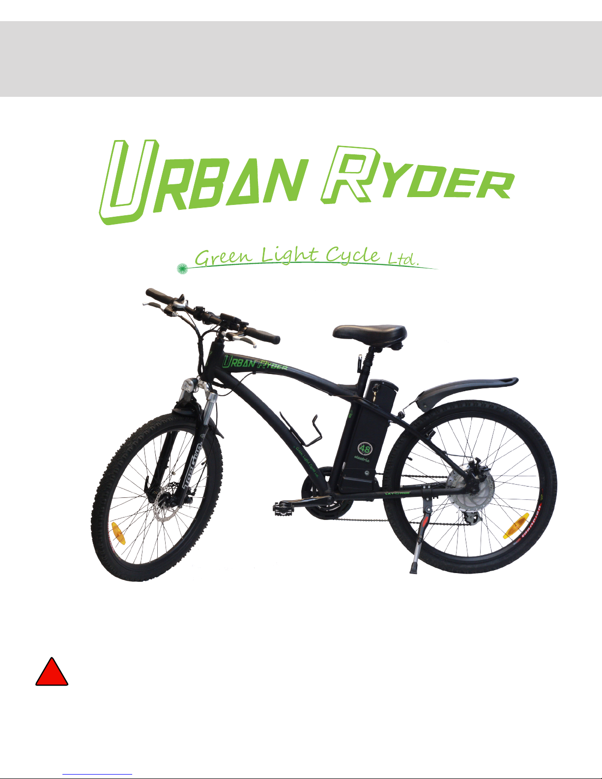
Green Light Cycle Urban Ryder Manual de usuario

WARNING: You are the only person responsible for your personal safety. Do not operate or ride any Power
Assisted Bicycle unless you are already a competent bicycle rider. The bike can quickly reach high
speeds, cauon must be exercised when operang the Urban Ryder. Carefully read the following
informaon (even if you are an experienced rider), wear a helmet and safety equipment, and obey
all Provincial and Federal motor vehicle laws. An unprotected head is highly suscepble to injury,
even from the lightest contact, but wearing a helmet that meets UL or CSA tesng standards may
help prevent injury. 10/09/13
USER MANUAL
POWER ASSISTED BICYCLES
By
!
™

2
USER MANUAL - URBAN RYDER™
www.greenlightcycle.com1-855-GRN-RYDE (1-855-476-7933)
TABLE OF CONTENTS
Table of Contents
Parts Identication Diagram..........................................................................................................................................3
Assembly Instructions...................................................................................................................................................4
Assemble the Bike: Handlebars........................................................................................................................... 5
Assemble the Bike: Front Wheel ........................................................................................................................6
Assemble the Bike: Front Wheel & Pedals ..........................................................................................................7
Assemble the Bike: Seat Installation & Tire Pressure......................................................................................... 8
Urban Ryder™ Operation: Battery Removal & Installation, Precautions, Charging, and Storage......................... 9
Removal & Install the Battery ..............................................................................................................................9
Charging the Battery..........................................................................................................................................10
Long Term Battery Care..................................................................................................................................... 11
Extending the Life of Your Battery .....................................................................................................................12
Urban Ryder™ Operation: System and Battery Power “ON/OFF”...........................................................................13
Introduction ........................................................................................................................................................13
Power Up Your E-Bike .......................................................................................................................................13
Using the King Meter®.......................................................................................................................................14
Time Setting.......................................................................................................................................................14
Top Riding Speed ...................................................................................................................................... 14
Display Units..............................................................................................................................................15
Wheel Diameter Setting.............................................................................................................................15
Backlight Brightness ..................................................................................................................................15
Exit Settings.......................................................................................................................................................15
Normal Operation of E-Bike...............................................................................................................................15
Power OFF ................................................................................................................................................15
Speed Display............................................................................................................................................15
Pedal Assist Level and Throttle Power Off/On Selection...................................................................................16
King Meter® Display Backlight and Bike Head Light.................................................................................16
Distance and Time Display ........................................................................................................................16
Battery Capacity ........................................................................................................................................16
Malfunction Codes .............................................................................................................................................17
Display Malfunction Codes ........................................................................................................................17
Button Battery Replacement.............................................................................................................................. 17
Pedal Assist & Thumb Throttle...........................................................................................................................17
Braking System..................................................................................................................................................17
Pre-Ride Checklist .............................................................................................................................................18
Pre-Ride Checklist and Familiarization Before Your First Ride ................................................................. 18
Operation of Power Assisted Bicycle Controls ..........................................................................................18
“10 Point” Check List .................................................................................................................................18
Urban Ryder™ Operation: Usage ...............................................................................................................................19
Urban Ryder™: Troubleshooting................................................................................................................................20
Urban Ryder™: Care & Maintenance..........................................................................................................................21
Transporting an Electric Bicycle......................................................................................................................... 21
Care & Cleaning ................................................................................................................................................22
Urban Ryder™: Warranty.............................................................................................................................................23
WARRANTY REGISTRATION INFORMATION CARD ................................................................................................. 24

3
1-855-GRN-RYDE (1-855-476-7933) www.greenlightcycle.com
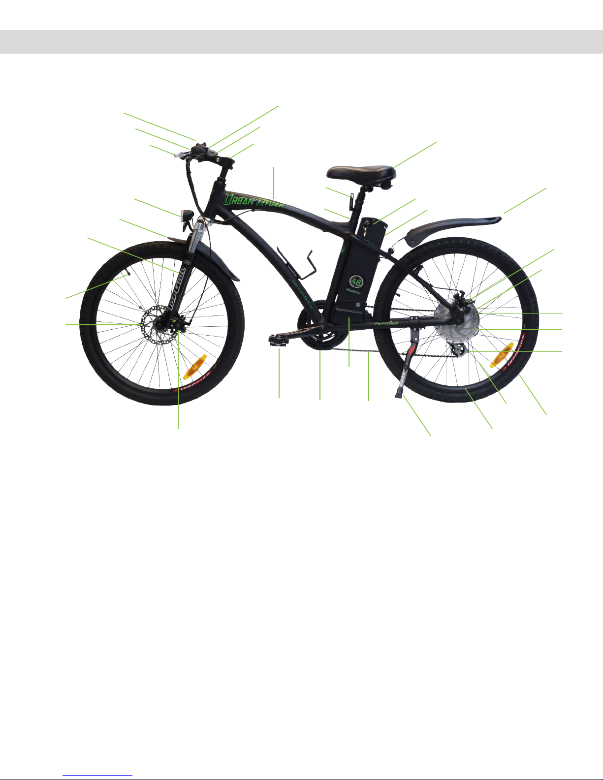
USER MANUAL - URBAN RYDER™ PARTS IDENTIFICATION DIAGRAM
1. Tektro® Front Disc Brake
2. Tire Valve Stem
3. Front Suspension
4. Front Fender
5. Front Light
6. Brake Levers
7. King Meter® LCD Display
8. Bell
9. Thumb Throle
10. Shi Lever
11. Handlebar
12. Frame
13. Seat Post
14. Quick Release Seat Lock
15. Seat
16. Baery Key
17. Baery
18. Rear Fender
19. Rear Brake Calliper
20. Tektro® Rear Disc Brake
21. Shimano® Freewheel
22. Hub Motor by 8FUN
23. Shimano® Derailleur
24. Tires
25. Spokes
26. Rims
27. Kickstand
28. Chain
29. Controller box
30. Chain Wheel and Crank
31. Pedals
32. Front Brake Calliper
Parts Identication Diagram
18
19
20
15
9
17
16
10
11
5
6
7
8
4
3
2
26
27
12
14
13
31
32
28
29
30 25
24
21
22
23
1

4
USER MANUAL - URBAN RYDER™
www.greenlightcycle.com1-855-GRN-RYDE (1-855-476-7933)
ASSEMBLY INSTRUCTIONS
Congratulaons on receiving your Urban Ryder™ Electric Bicycle!
Open the box from the top by cung the 3 bands and the packaging tape. Carefully remove the 3 styrofoam packing
blocks. Remove the front wheel before removing the bicycle. Remove the bicycle by liing it straight out of the box (may
require 2 people). Be careful not to scratch yourself or the bike on the carton. Stand the bike on a clean at surface and
remove the styrofoam packing material strap ed to the frame and various parts. Be careful not to scratch the bike or cut
yourself when snipping the strap es. Be sure to keep any small packages of parts and paperwork that come with the bike.
Check all contents to ensure you have each part required for assembly.
Box Contents:
1 x Bike Frame with Rear Wheel Aached
1 x Front Wheel
2 x Pedals (Le & Right)
1 x Lithium Baery 48 Volts 10Ah
2 x Baery Keys
1 x 120 Volt Charger
1 x Seat
1 x Tool Kit: 5 x Hex Wrenches (2mm, 3mm, 4mm, 5mm, 6mm)
3 x Wrenches, double sided (8mm & 10mm, 13mm & 15mm, 14mm & 17mm)
1 x Screwdriver, double sided (star & slot conguraon)
1 x King Meter® Owner’s Manual
1 x Shimano® Gear and Tektro® Brake Data Sheets
1 x Green Light Cycle Owner’s Manual
Now that you have your bike out of the box and unpacked, it is me to charge the baery. Please refer to the Baery
Removal & Installaon, Precauons, Charging, and Storage instrucons on page 10. It is beer to remove the baery from
the bike for the rst charging as this will make the bike assembly easier, with no cords in your way.
Assembly Instructions
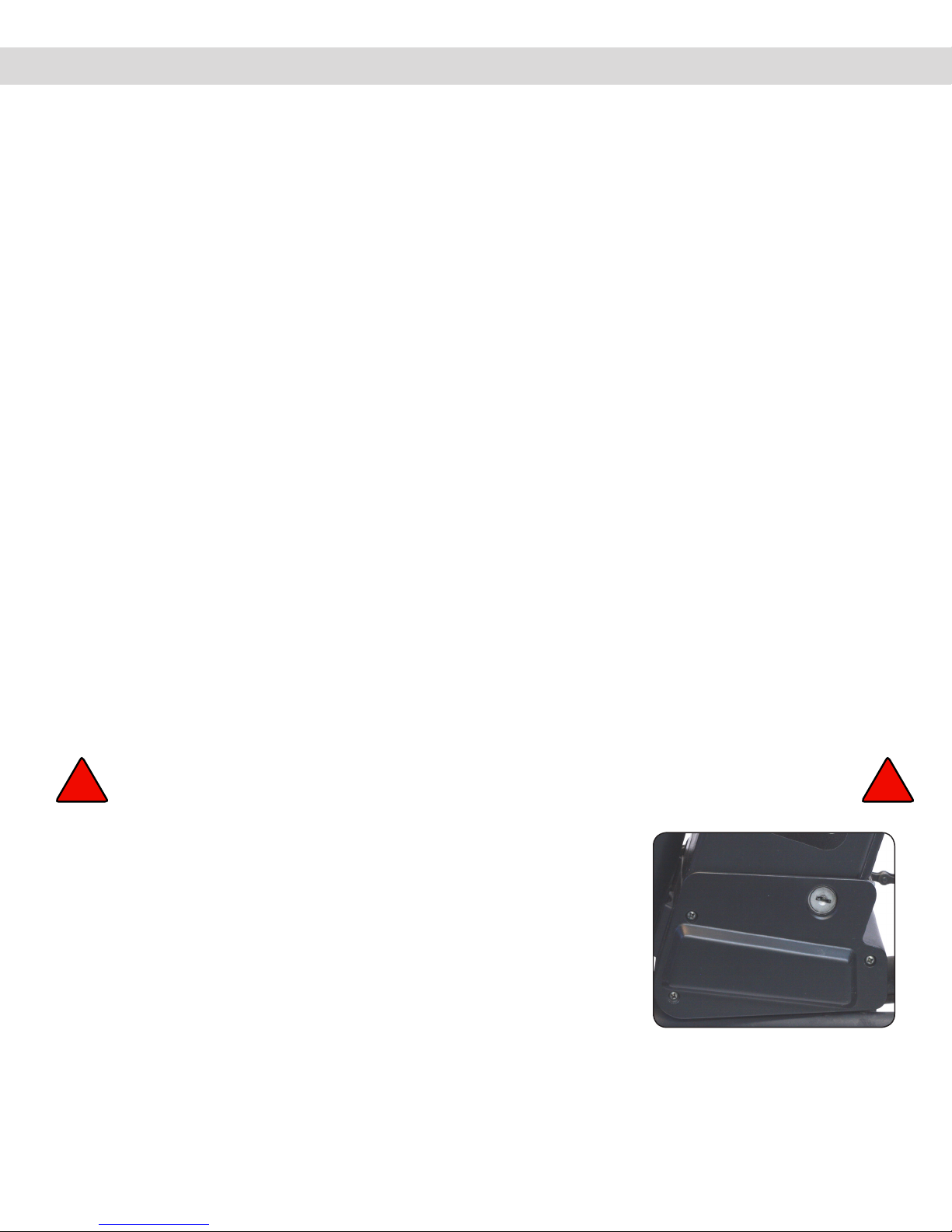
Battery Lock
Unlock the baery with the key by inserng the key in the boom lock close to
the frame. Turn the key one half turn counter clockwise to unlock and remove
the key. Pull the baery straight up by the folding handle to remove from the
bike. Follow the charging instrucons to complete the baery to full charge.
Reinstall the baery into the bike aer you have completed the bike assembly.
WARNING: Please keep the keys to your electric bicycle in a safe place. Each set of keys are unique to
your parcular electric bicycle and we do not keep a copy of your key on le. !!

5
1-855-GRN-RYDE (1-855-476-7933) www.greenlightcycle.com
USER MANUAL - URBAN RYDER™ ASSEMBLE THE BIKE: HANDLEBARS
Tools required (received in your Tool Kit):
5 x Hex Wrenches (2mm, 3mm, 4mm, 5mm, 6mm)
3 x Wrenches, double sided (8mm & 10mm, 13mm & 15mm, 14mm & 17mm)
1 x Screwdriver, double sided (star & slot conguraon)
Assemble the Bike: Handlebars
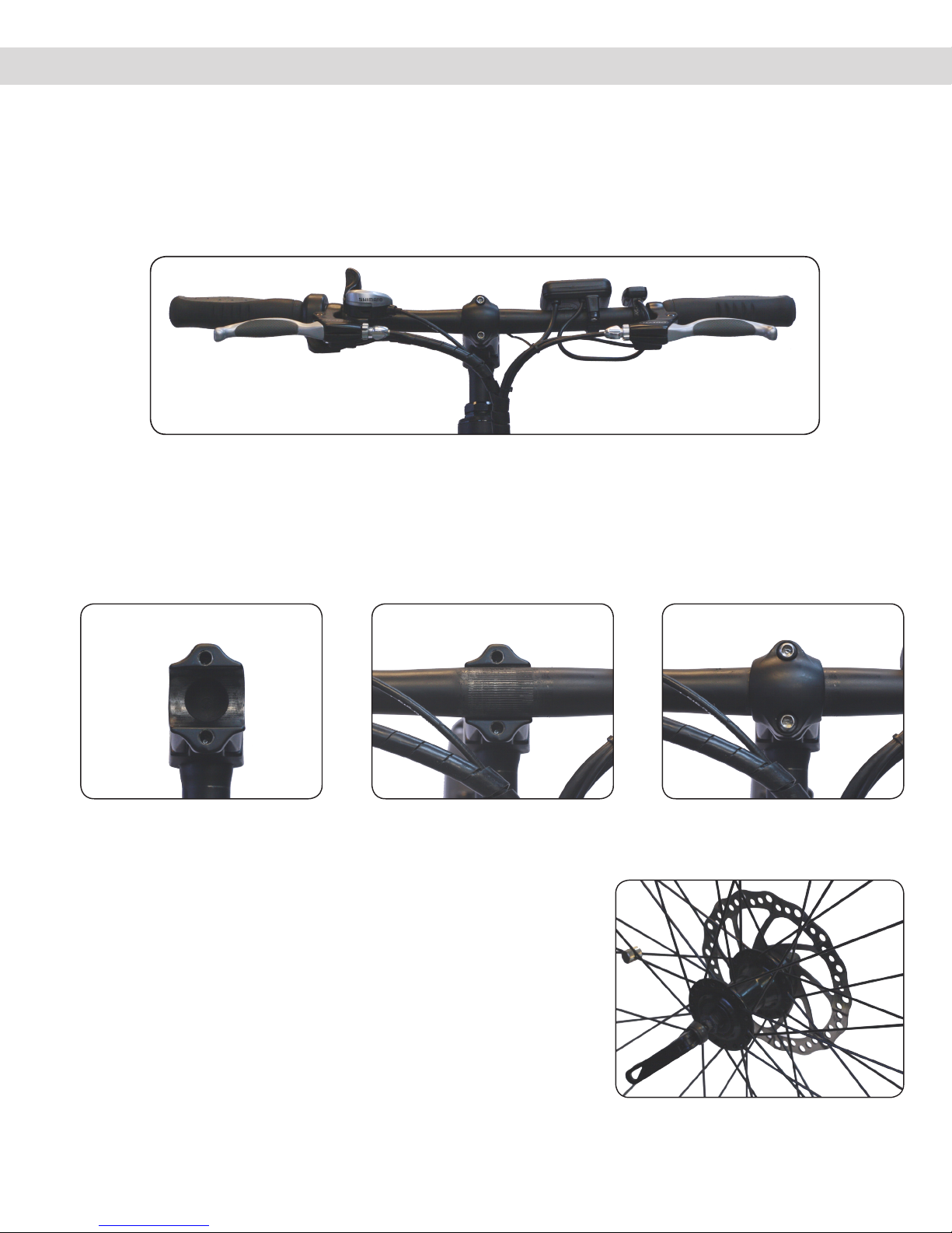
1. Handlebars
Install the handlebars by removing the 2 stem faceplate bolts. Turn the handlebar to ensure that the wiring is not twisted
and ows upward toward the handlebars without kinking. Place the handlebars in the half round stem cut-out making sure
that the grooves (splines) are aligned correctly, in the centre of the cut-out. Replace the faceplate and ghten the bolts
evenly so that the faceplate sits at over the handlebar.
Fig. 1.1 Handlebars
Fig. 1.2 Handlebar Stem Cut-out Fig. 1.3 Handlebar Stem With
Handlebar Inserted
Fig. 1.4. Handlebar Face-
plate With Tight-
ened Bolts
Fig 1.5. Quick Release Lever, Front
Wheel
Quick Release Lever on the Front Wheel
Urban Ryder™ uses a quick release lever to lock the front wheel into
the fork dropouts. Quick release levers are safe and convenient when
adjusted properly. Before riding your bicycle you must understand how
they work and how to use them properly to prevent serious injury or
death from a fall.
Quick release levers use a cam acon to clamp the front wheel in place.
Due to their adjustable nature, it is crical that you understand how they
work, their proper use, and how much force is needed to secure them
correctly.

6
USER MANUAL - URBAN RYDER™
www.greenlightcycle.com1-855-GRN-RYDE (1-855-476-7933)
ASSEMBLE THE BIKE: FRONT WHEEL
CAUTION: The full force of the cam acon is needed to clamp the wheel securely. Holding the nut with
one hand and turning the lever like a wing nut, is NOT a safe or eecve way to close a quick
release and will not clamp the wheel safely to the forks.
WARNING: Operang the bike with an improperly adjusted wheel or Quick Release Lever, can allow the
wheel to wobble or fall o the bicycle. This can cause serious injury or death.
Assemble the Bike: Front Wheel
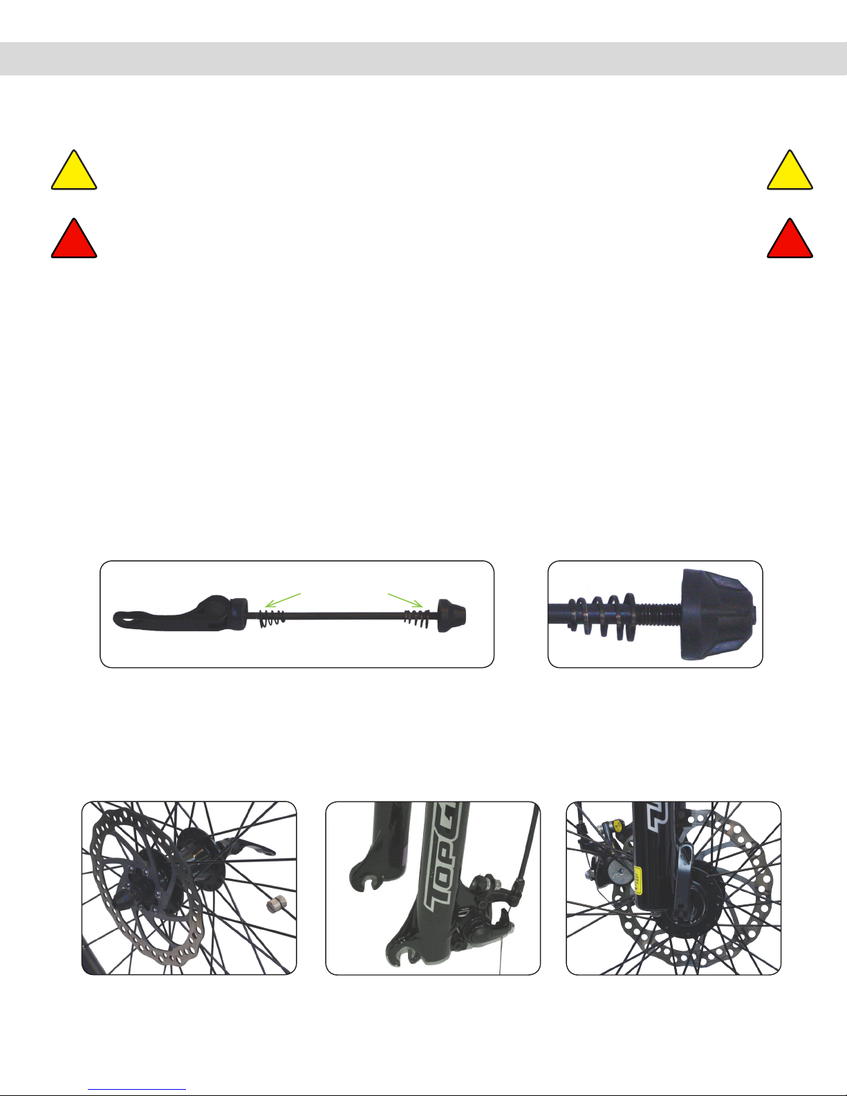
2. Installing the Front Wheel
Install the front wheel by rst inserng the Quick Release rod into the wheel axel. There are 2 small springs on the Quick
Release rod that have dierent diameters on each end. Install the springs so that the ends with the larger diameter are
next to the Quick Release and the round nut. Make sure the round black nut is on the disc side of the wheel and the lock
lever is on the opposite side.
Tighten the round nut onto the rod so the rod threads are almost ush with the outside of the nut. Be careful not to cross
the threads and ghten by hand only.
Place the Quick Release Lever in the open posion. Have someone hold and li the bike by the handlebars to posion the
front wheel into the forks. Make sure that you line up the brake disc with the brake calliper when inserng the front wheel
axel into the fork drop outs. Check to ensure that the axel has engaged all the way into the fork dropouts before clamping.
Fig. 2.1 Front Wheel Quick Release Fig. 2.2 Quick Release Nut &
Rod Thread
Fig. 2.3 Front Wheel, Quick
Release Inserted Into
Wheel Axle
Fig. 2.4 Front Forks & Brake
Calliper
Fig. 2.5 Quick Release Lever
In Closed Position
! !
It is essenal that you know how to install and remove your wheels safely. If you are unsure ask your local bike shop to
install or assemble your bike and wheels. Understand and apply the correct technique for clamping your wheel in place
with a Quick Release Lever. Before each ride of your bike, check that the wheel is securely clamped properly and the Quick
Release Lever is in the correct posion and locked.
!!
Larger
Diameter to
Outsides

7
1-855-GRN-RYDE (1-855-476-7933) www.greenlightcycle.com
USER MANUAL - URBAN RYDER™ ASSEMBLE THE BIKE: FRONT WHEEL
To ghten the Quick Release and axel into the fork dropout, ensure the Quick
Release is in the open posion with the lever parallel to the ground (the lever
should be at a 90° angle to the forks). With the lever in this posion, ghten
the round nut nger ght. You will not be able to close the lever to the locked
posion yet.
Next, loosen the nut approximately 3 quarter turns (counter clockwise) and li
the lever upward to lock the wheel in place. The lever should be almost parallel
to the front fork when locked. If the tension is correct, the lever should close
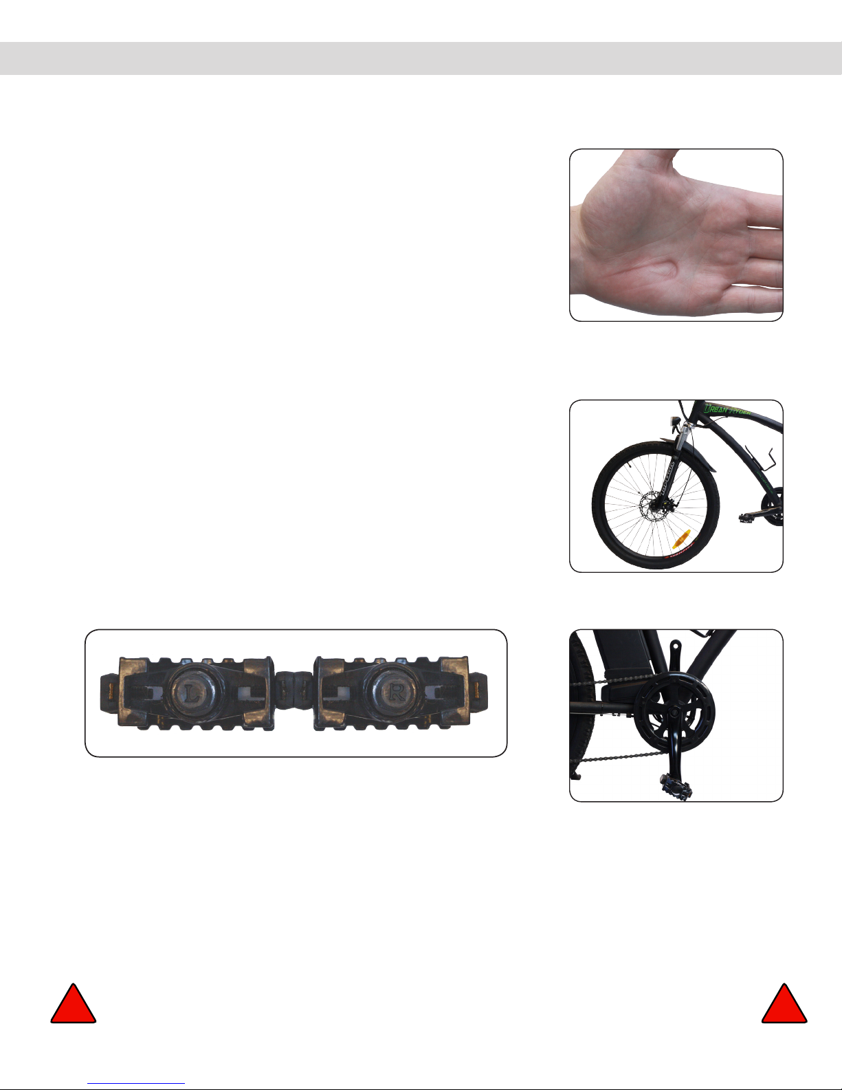
ghtly. When closing the lever it should leave a clear imprint in the palm of
your hand (the imprint may not be as deep as the hand model’s picture).
When the lever is locked in this posion (parallel to the fork), it will not easily
be opened if it catches on any objects while riding your bike. To increase or
decrease the tension, open the lever and adjust the nut clockwise or counter
clockwise, 1/8 turn at a me. Repeat unl the tension is sucient. Less than
1/2 a turn on the adjusng nut can make the dierence between safe clamping
force and unsafe clamping force.
Assemble the Bike: Front Wheel
Fig. 2.7 Forks Secured Onto
Front Wheel
Fig. 2.6 Imprint of Quick
Release Lever After
Correctly Closed
Fig. 3.2 Crank Arm, Right
Pedal Inserted
Fig. 3.1 Left & Right Pedals
3. Pedal Installaon
Note: “L” and “R” (“L”=le & “R”=right) is stamped on the threaded ends of the
pedals. The pedals have opposite thread direcons and must go on a specic
side of the bike. Le and right side of the bike is determined by sing on the
seat.
The Le Pedal has a reverse, non-standard thread and must be turned counter
clockwise to be screwed in.
The Right Pedal has a standard thread and must be turned clockwise to be threaded in.
Apply some grease to the pedal threads before aaching. Install the Right Pedal to the chain sprocket side of the bike and
the Le Pedal to the opposite side (same side as the baery key).
Start the pedal threads into the crank arm threads, by hand, at least 4 complete 360° turns to ensure the pedals are not
cross-threaded. Incorrect installaon of the pedals is not covered under warranty. Complete by securely ghtening with a
15mm wrench.
WARNING: Poorly ghtened pedals can result in injury or death. !!

8
USER MANUAL - URBAN RYDER™
www.greenlightcycle.com1-855-GRN-RYDE (1-855-476-7933)
ASSEMBLE THE BIKE: SEAT INSTALLATION
4. Seat Installaon
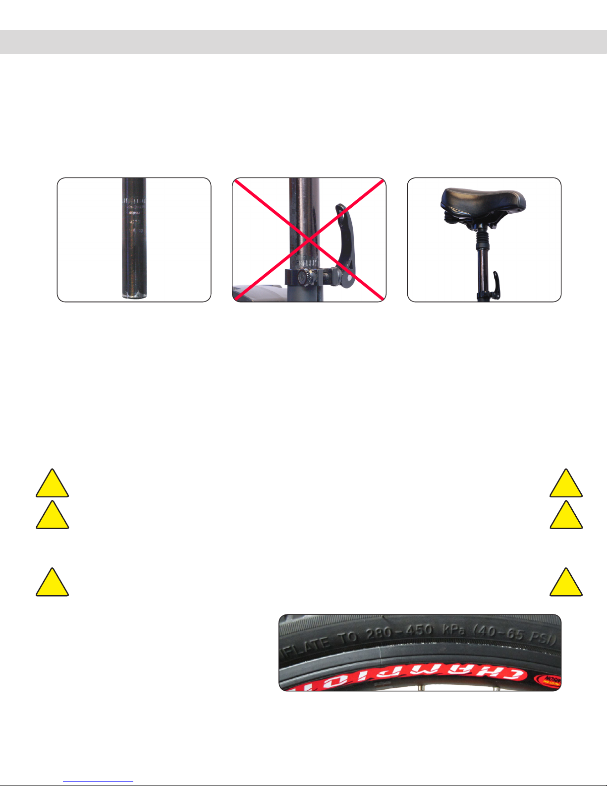
Idenfy the “Minimum Insert Line” on the seat post. Insert the seat post into the seat tube so the Minimum Insert Line is
not visible. The seat post sha must be installed so that the Minimum Insert Line is below the Quick Release Lever.
Assemble the Bike: Seat Installation
Fig. 4.1. Seat Post,
“Minimum Insert
Line”
Fig. 4.3 Seat Post Inserted
Correctly, Past
“Minimum Insert
Line”
Fig. 4.2 Incorrectly Installed
Seat Post
With the Quick Release Lever in the open posion (the lever should be at a 90° angle to the seat tube), insert the seat post
into the seat tube. Tighten the Quick Release clamp by turning the tension adjusng nut clockwise, with one hand on the
cam lever to keep it from rotang. Li the Quick Release Lever up to the locked posion.
Grab the seat by the saddle with both hands to aempt to rotate the seat. If you are unable to force the seat out of
alignment with the frame the clamp is ght enough. If the seat moves out of alignment with the frame, increase the
tension on the adjusng nut approximately a 1/4 turn and try again. The seat height can be adjusted from 37.4 - 42.1
inches (950mm - 1070mm).
Fig. 5.1 Tire Pressure Ratings
CAUTION: Less than 1/2 a turn on the adjusng nut can make the dierence between safe clamping force
and unsafe clamping force.
CAUTION: A poorly adjusted seat can result in personal injury or death.
!!
!!
CAUTION: The res have NOT been lled with air to the correct capacity for shipping purposes. !!
5. Tire Pressure
Using a hand pump, ll the res with air to the
rang on the sidewall. We recommend a hand
pump to avoid over inang the res, which can
easily happen when using a high pressure air line
at a gas staon or automove re store.
The res are rated for a maximum of pressure of
“450 kPa” or “65 PSI”.

9
1-855-GRN-RYDE (1-855-476-7933) www.greenlightcycle.com
USER MANUAL - URBAN RYDER™ URBAN RYDER™ OPERATION: BATTERY
6. Remove and Install the Baery
Urban Ryder™ Operation: Battery - Removal & Installation, Precautions, Charging, and Storage
Fig. 6.1 Battery Lock
CAUTION: Fully charge the baery before the rst use!
Failure to do this can result in decreased baery
performance for the life of the bike and void your
baery warranty.
CAUTION: Do not aempt to open or repair your baery or
charger. If you need another baery or charger
contact your dealer or Green Light Cycle Ltd.™
CAUTION: Do not touch the baery sockets or blades with
your hands, any metal object or other material that
conducts electricity.
CAUTION: Never put the baery or charger in reach of
children.
CAUTION: Do not use any charger except the one that came
with your Urban Ryder™ Electric Bike.
Fig. 6.2 Battery - 1/2”
Rounded Edge
Towards Seat Post
Lithium Baery Precauons
!
!
!
!
!
!
!
!
!
!
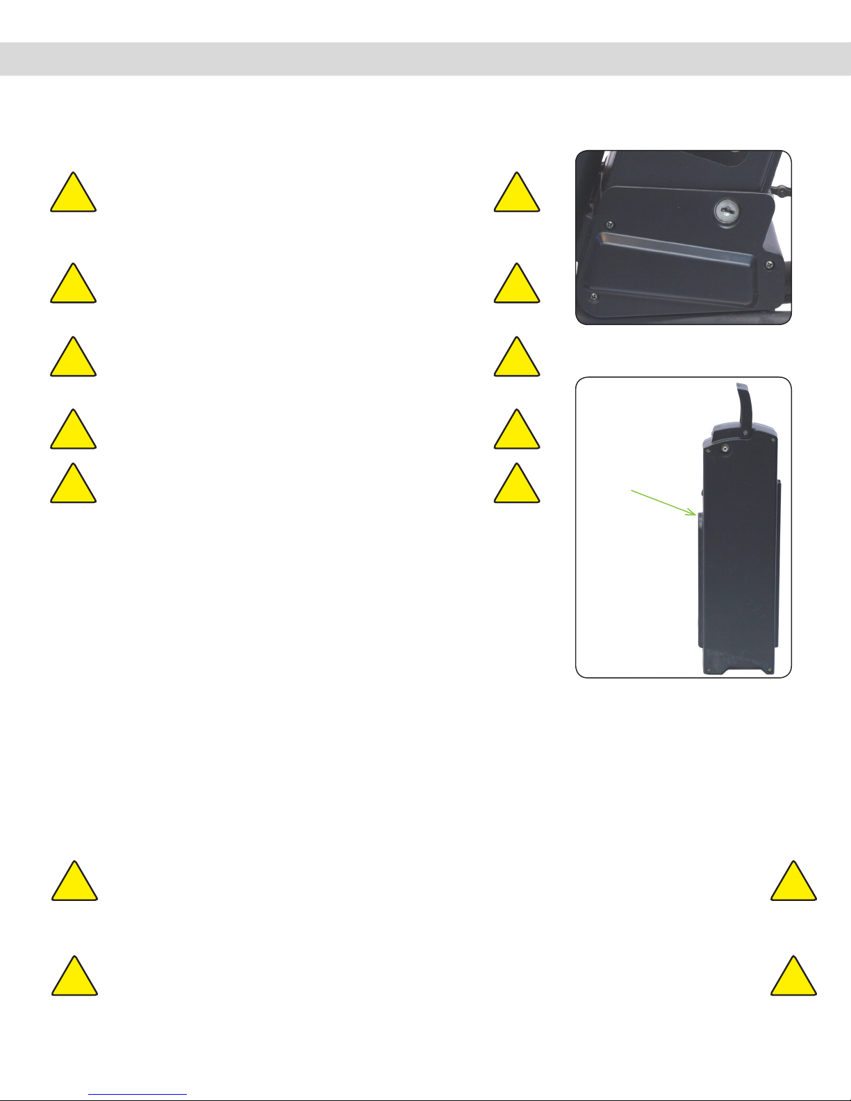
Unlock the baery from the controller box by inserng the baery key into
the lock, located on the boom of the baery near the crank arm and pedals.
Remove the key before trying to li the baery away from the bike. Remove
the seat or turn it sideways to slide the baery straight up and out of the cradle,
using one hand on the folding handle and the other hand to hold the bike
steady.
Install the baery in the reverse order of removal. Ensure the top of the
controller box, where the base of the baery rests, is clear of any dirt or debris.
Slide the baery into the grooved cradle with the 1/2” rounded edge against the
seat post tube, unl the baery base rests ghtly onto the controller box and
the connecng blades are rmly in the baery sockets.
1/2”
Rounded
Edge
Do not use excessive force to t the baery into the base, as it could damage the connecon sockets or blades. Be sure to
always lock the baery aer placing in the cradle.
CAUTION: Do not aempt to open or repair your baery. This may cause electrical shock or re and
will void your warranty. Should you have a problem or need another baery contact Green
Light Cycle Ltd.™ Should your baery become hot, emit smoke or unusual orders, remove the
baery to a dry area outside immediately.
CAUTION: Fully charge the baery before the rst use! Failure to do this can result in decreased baery
performance for the life of the bike and void your warranty.
!
!
!
!

10
USER MANUAL - URBAN RYDER™
www.greenlightcycle.com1-855-GRN-RYDE (1-855-476-7933)
URBAN RYDER™ OPERATION: BATTERY
As lithium baeries do not suer from Memory Eect, it is not required for the baery to be empty to begin a charge. Top
up charging every me you have completed your ride is recommended. A new baery might take 2 or 3 charges before it
performs at its full capacity. All baeries have a nite life cycle and eventually lose storage capacity below a useful level.
Kept in good condion, a lithium baery will perform at least 300 to 900 full charge cycles with a retenon of 70% from its
original capacity. Small top up charges count fraconally towards a single full cycle charge. The baery may be charged on
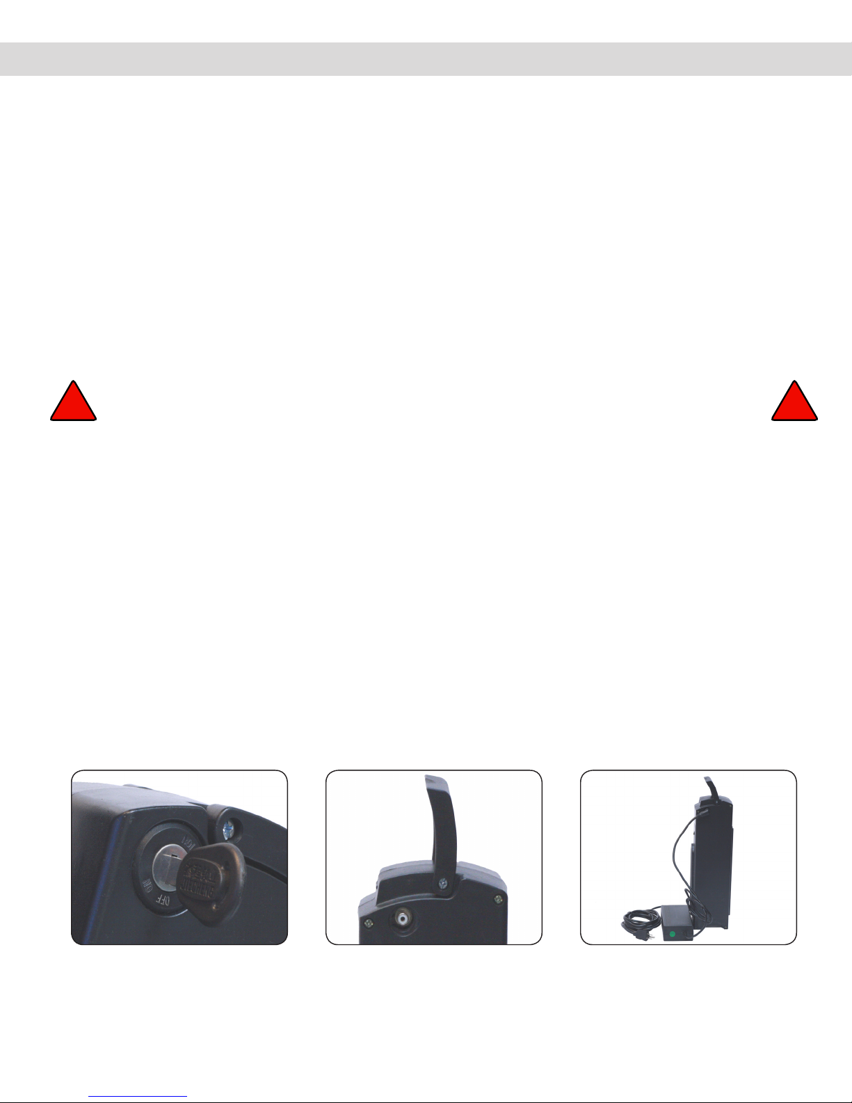
or o the bike. Always charge the baery with the key in the “OFF” posion. Never charge a hot baery or immediately
aer a long ride; let the baery cool for approximately 1 hour prior to charging.
Do not leave the charger plugged into the baery for long periods of me, as this can damage the baery. Always charge
the bike in a dry, clean place. Keep the charger dry and clean. Avoid storing your baeries in extreme temperatures, hot or
cold, and keep in a cool dry place. Always plug the baery charger into a grounded ELECTRICAL circuit.
The baery can be used in any weather between 1°C to 38°C. Extreme heat or extreme cold can shorten the baery range.
Try to avoid fully discharging the baery. It may be possible aer the baery is discharged to turn o the bike, wait a few
seconds, and turn it back on to get a small amount of power. This “pulsing” (turning o and on) will permanently damage
the baery. Lithium baeries prefer frequent paral discharge charge cycles rather than fewer, full, deep cycle charges.
To prevent premature failure of your baery and for your warranty to remain in eect, you must charge and discharge the
baery at least once per month.
7. Charging the Baery
The supplied baery is a Lithium, 48 Volts and 10amp hours. Check to ensure that the charger voltage is correct for your
baery. The charger should read “Output 55VDC 2A”. Only use a wall receptacle with a grounded circuit to plug your
charger into.
Fig. 7.1 Battery Key - OFF Fig. 7.3 Battery & Charger
Fig. 7.2 Battery Charging
Port
WARNING: Never charge the baery outside in wet weather, as there is a chance of electrical shock,
electrocuon, and death.
! !
Urban Ryder™ Operation: Battery - Removal & Installation, Precautions, Charging, and Storage
Otros manuales para Urban Ryder
1
Este manual sirve para los siguientes modelos
1
Tabla de contenidos
Otros manuales de Bicicleta de Green Light Cycle