Graco QUANTM 25F108 Manual de usuario

3A8861C
EN
Instructions
QUANTM™ Leak Sensors
For detecting leaks in QUANTM pumps. For professional use only.
Kit for pumps certified for use in Ordinary
Locations
Kit for pumps certified for use in Explosive
Atmospheres or Hazardous (Classified) Locations
Important Safety Instructions
Read all warnings and instructions in this
manual and related system manuals
before using or servicing the equipment.
Save these instructions.
Kit No. Kits include:
25F108 1 level switch sensor
1 reducer fitting
2 elbow swivels (1/4 in. NPT; 3/8 in. hose
port)
1 tee union
1 hose (30 in. long, 3/8 in. outer diameter)
1 breather
Kit No. Kits include:
25F109 1 level switch sensor
2 elbow swivels (1/4 in. NPT; 3/8 in. hose
port)
1 tee union
1 hose (30 in. long, 3/8 in. outer diameter)
1 breather (For shipping purposes only.
Discard.)
1 elbow swivel (1/4 in. NPT; 1/4 in. hose
port)
1 elbow swivel (1/8 in. NPT)
1 hose (20 in. long, 1/4 in. outer diameter)
1 pipe bushing

2 3A8861C
Contents
Related Manuals . . . . . . . . . . . . . . . . . . . . . . . . . . . . 2
Warnings . . . . . . . . . . . . . . . . . . . . . . . . . . . . . . . . . . 3
Overview . . . . . . . . . . . . . . . . . . . . . . . . . . . . . . . . . . 6
Component Identification . . . . . . . . . . . . . . . . . . . . 6
Installation. . . . . . . . . . . . . . . . . . . . . . . . . . . . . . . . . 7
Prepare the Pump . . . . . . . . . . . . . . . . . . . . . . . . 7
Install the Leak Sensor. . . . . . . . . . . . . . . . . . . . . 7
Install Hoses and Fittings. . . . . . . . . . . . . . . . . . . 9
Test the Leak Sensor . . . . . . . . . . . . . . . . . . . . . 12
Electrical Schematics. . . . . . . . . . . . . . . . . . . . . . . 13
Technical Specifications . . . . . . . . . . . . . . . . . . . . 13
California Proposition 65 . . . . . . . . . . . . . . . . . . . . 13
Graco Standard Warranty. . . . . . . . . . . . . . . . . . . . 14
Related Manuals
English Manual
Number Description Reference
3A7637 QUANTM Electric Motor, Repair-Parts Motor Manual
3A8572 QUANTM Pumps, Instructions, Industrial Models Pump Manual
3A9286 QUANTM Pumps, Instructions, Hygienic Models Pump Manual
3A8946 QUANTM Pumps, Parts, Industrial Models Parts Manual
3A9287 QUANTM Pumps, Parts, Hygienic Models Parts Manual

Warnings
3A8861C 3
Warnings
The following warnings are for the setup, use, grounding, maintenance, and repair of this equipment. The
exclamation point symbol alerts you to a general warning and the hazard symbols refer to procedure-specific risks.
When these symbols appear in the body of this manual or on warning labels, refer back to these Warnings.
Product-specific hazard symbols and warnings not covered in this section may appear throughout the body of this
manual where applicable.
WARNING
FIRE AND EXPLOSION HAZARD
Flammable fumes, such as solvent and paint fumes, in work area can ignite or explode. Paint or
solvent flowing through the equipment can cause static sparking. To help prevent fire and explosion:
• Use equipment only in well-ventilated area.
• Eliminate all ignition sources; such as pilot lights, cigarettes, portable electric lamps, and plastic
drop cloths (potential static sparking).
• Ground all equipment in the work area. See Grounding instructions in your pump manual.
• Keep work area free of debris, including solvent, rags and gasoline.
• Do not plug or unplug power cords, or turn power or light switches on or off when flammable fumes
are present.
• Use only conductive grounded fluid lines.
•Stop operation immediately if static sparking occurs or you feel a shock. Do not use equipment
until you identify and correct the problem.
• Keep a working fire extinguisher in the work area.
Static charge may build up on plastic parts during cleaning and could discharge and ignite flammable
vapors. To help prevent fire and explosion:
• Clean plastic parts only in well-ventilated area.
• Do not clean with a dry cloth.

Warnings
4 3A8861C
ELECTRIC SHOCK HAZARD
Explosive Atmospheres or Hazardous (Classified) Locations Pumps (hard wired for permanent
connection):
This equipment must be grounded. Improper grounding, setup, or usage of the system can cause
electric shock.
• Turn off and disconnect power at main switch before disconnecting any cables and before servicing
or installing equipment.
• Connect only to grounded power source.
• All electrical wiring and repairs must be done by a qualified electrician and comply with all local
codes and regulations.
• Do not expose to rain. Store indoors.
Ordinary Locations Pumps (cord and plug connection)
This equipment must be grounded. Improper grounding, setup, or usage of the system can cause
electric shock.
• Turn off and disconnect power cord before servicing equipment.
• Connect only to grounded electrical outlets.
• Only use 3-wire extension cords for 2-phase models. Only use 4-wire extension cords for 3-phase
models.
• Ensure ground prongs are intact on power and extension cords.
• Do not expose to rain. Store indoors.
• Wait five minutes after disconnecting power cord before servicing.
PRESSURIZED EQUIPMENT HAZARD
Fluid from the equipment, leaks, or ruptured components can splash in the eyes or on skin and cause
serious injury.
• Follow the Pressure Relief Procedure in your pump manual when you stop spraying/dispensing
and before cleaning, checking, or servicing equipment.
• Tighten all fluid connections before operating the equipment.
• Check fluid lines and connections daily. Replace worn or damaged parts immediately.
WARNING

Warnings
3A8861C 5
EQUIPMENT MISUSE HAZARD
Misuse can cause death or serious injury.
• Do not operate the unit when fatigued or under the influence of drugs or alcohol.
• Do not exceed the maximum working pressure or temperature rating of the lowest rated system
component. See Technical Specifications in all equipment manuals.
• Use fluids and solvents that are compatible with equipment wetted parts. See Technical
Specifications in all equipment manuals. Read fluid and solvent manufacturer’s warnings. For
complete information about your material, request Safety Data Sheets (SDSs) from distributor or
retailer.
• Turn off all equipment and follow the Pressure Relief Procedure in your pump manual when
equipment is not in use.
• Check equipment daily. Repair or replace worn or damaged parts immediately with genuine
manufacturer’s replacement parts only.
• Do not alter or modify equipment. Alterations or modifications may void agency approvals and
create safety hazards.
• Make sure all equipment is rated and approved for the environment in which you are using it.
• Use equipment only for its intended purpose. Call your distributor for information.
• Route fluid lines, cords, and cables away from traffic areas, sharp edges, moving parts, and hot
surfaces.
• Do not kink or over-bend fluid lines, cords, or cables. Do not use fluid lines, cords, or cables to pull
equipment.
• Keep children and animals away from work area.
• Comply with all applicable safety regulations.
BURN HAZARD
Equipment surfaces and fluid that is heated can become very hot during operation. To avoid severe
burns:
• Do not touch hot fluid or equipment.
PERSONAL PROTECTIVE EQUIPMENT
Wear appropriate protective equipment when in the work area to help prevent serious injury, including
eye injury, hearing loss, inhalation of toxic fumes, and burns. Protective equipment includes but is not
limited to:
• Protective eyewear, and hearing protection.
• Respirators, protective clothing, and gloves as recommended by the fluid and solvent
manufacturer.
WARNING

Overview
6 3A8861C
Overview
The leak sensor monitors the equipment for diaphragm rupture or other leaks in the equipment. If the sensor
detects a leak, the LED indicator on the pump will flash and the pump will stop.
Component Identification
FIG. 1: Leak Sensor Kit for Pumps Certified for Use in
Ordinary Locations
Key:
FIG. 2: Leak Sensor Kit for Pumps Certified for Use in
Explosive Atmospheres or Hazardous (Classified)
Locations
ALeak sensor wire
B* Reducer fitting
CLeak sensor
DFitting, elbow swivel (1/4 in. NPT; 3/8 in. hose port)
ETee union
FHose (3/8 in. outer diameter)
G‡Fitting, elbow swivel (1/8 in. NPT)
H‡Hose (1/4 in. outer diameter)
J‡Fitting, pipe bushing
K*♦Fitting, breather
N‡Fitting, elbow swivel (1/4 in. NPT; 1/4 in. hose port)
A
C
B
D
E
F
K
* Only for pumps certified for use in Ordinary Locations.
♦ Discard for pumps certified for use in Explosive
Atmospheres or Hazardous (Classified) Locations.
‡ Only for pumps certified for use in Explosive
Atmospheres or Hazardous (Classified) Locations.
A
C
D
E
F
H
G
N
J
K

Installation
3A8861C 7
Installation
Prepare the Pump
Always complete the following procedure before
performing any service or repair to the equipment.
1. Relieve the pressure. Follow the Pressure Relief
Procedure in your related pump manual. See
Related Manuals, page 2.
2. Verify that the pump is turned off and power to the
system is disconnected before performing any
service or repair procedure.
Install the Leak Sensor
See FIG. 3–FIG. 4.
Required Tools:
• 7/8 in. open-end wrench
• 3/8 in. hex wrench
• 3/4 in. open-end wrench (for pumps certified for
use in Ordinary Locations only)
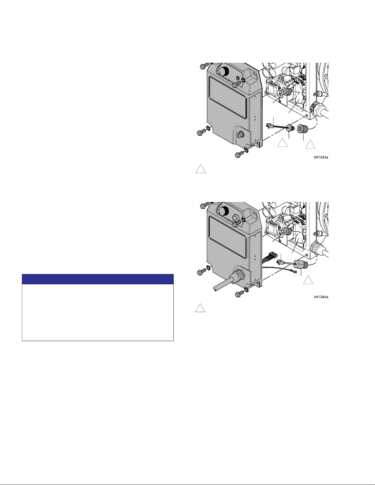
Remove the Leak Sensor
If a leak sensor is currently installed, remove the current
leak sensor before installing the new leak sensor.
1. Follow Prepare the Pump, page 7.
2. Remove the control cover. See your related motor
manual. See Related Manuals, page 2.
3. Disconnect the leak sensor wire (A) from the port in
the control housing (S). See Electrical
Schematics, page 13.
4. Pumps Certified for Use in Ordinary Locations
only: Loosen the fitting (B) behind the leak sensor
(C).
5. Remove the leak sensor (C) assembly and reducer
fitting (B, if applicable) from the control housing (S).
NOTE: Ensure there is no fluid in the leak sensor or
in the control housing.
6. Pumps Certified for Use in Ordinary Locations
only: Disconnect the fitting (B) from the leak
sensor (C).
7. Disconnect the hoses (F, H, if applicable) and
fittings (D, J, if applicable, K, if applicable, N, if
applicable) from the pump.
8. Inspect for wear or damage. Replace as necessary.
To avoid injury from fire, explosion, or electric
shock, all electrical wiring must be done by a
qualified electrician and comply with all local codes
and regulations.
To prevent electric shock, turn off the pump and
disconnect from power before performing any
service or repair procedure.
To help prevent serious injury from pressurized fluid,
such as skin injection, splashing fluid and moving
parts, relieve the pressure when you stop operating
and before cleaning, checking, or servicing the
equipment. Follow the Pressure Relief Procedure in
your related pump manual. See Related Manuals,
page 2.
Perform Prepare the Pump, page 7, before
performing any service or repair.
Pumps Certified for Use in Explosive
Atmospheres or Hazardous (Classified)
Locations: To avoid injury from fire and explosion,
move the equipment to a non-explosive or
non-hazardous location before performing any
service or repair to the equipment.
To avoid injury from electric shock, all electrical
wiring must be done by a qualified electrician and
comply with all local codes and regulations.
NOTICE
To avoid damage to the control board, ensure that
fluid does not contact electrical components in the
control housing.

Installation
8 3A8861C
Install the Leak Sensor
1. Follow Prepare the Pump, page 7.
2. Remove the control cover. See your related motor
manual. See Related Manuals, page 2.
3. If installing a leak sensor for the first time, remove
the plug (T).
4. Turn the switch for the leak sensor to the ON
position. See Electrical Schematics, page 13.
5. Apply a watertight thread sealant to the threads on
the leak sensor (C).
NOTE: To ensure a watertight seal, apply
Loctite 425 Assure™ thread sealant to the threads
on the leak sensor (C).
6. Pumps Certified for Use in Ordinary Locations
only: Install the leak sensor (C) to the reducer fitting
(B).
7. Pumps Certified for Use in Ordinary Locations
only: Apply a watertight thread sealant to the
threads on the reducer fitting (B).
NOTE: To ensure a watertight seal, apply
Loctite 425 Assure™ thread sealant to the threads
on the reducer fitting (B).
8. Install the leak sensor (C) assembly to the control
housing (S).
9. Pumps Certified for Use in Ordinary Locations
only: Securely tighten the reducer fitting (B) behind
the leak sensor (C).
10. Connect the leak sensor wire (A) to the port in the
control housing (S). See Electrical Schematics,
page 13.
NOTE: Ensure the switch for the leak sensor is
turned to ON.
11. Install the control cover. See your related motor
manual. See Related Manuals, page 2.
12. Connect the hoses and fittings to the pump. Follow
Install Hoses and Fittings, starting on page 9.
NOTICE
Ensure that the leak sensor is installed tightly so that
fluid cannot enter the control housing. Do not
overtighten. Excessive tightening could strip the leak
sensor threads.
After reassembly, allow the thread sealant to cure for
12 hours, or per instructions of the manufacturer,
prior to operating the system.
FIG. 3: Leak Sensor, Pumps Certified for Use in Ordinary
Locations
FIG. 4: Leak Sensor, Pumps Certified for Use in Explosive
Atmospheres or Hazardous (Classified) Locations
AS
1
Apply Loctite 425 Assure™ thread sealant
to the threads.
1
1B
C
T
A
S
1
C
Apply Loctite 425 Assure™ thread sealant
to the threads.
1
T

Installation
3A8861C 9
Install Hoses and Fittings
Required Tools:
• 3/16 in. hex wrench (for all models)
• 12 mm open-end wrench (for pumps certified for
use in Ordinary Locations only)
For pumps certified for use in Explosive Atmospheres
or Hazardous (Classified) Locations only:
• 3/8 in. hex wrench
• 10 mm socket wrench
• 9/16 in. open-end wrench
• 11/16 in. open-end wrench
• 13/16 in. open-end wrench
• 9/32 in. open-end wrench
• 1 in. open-end wrench
Prepare Equipment for Hoses and Fittings
Complete the following procedure before installing leak
sensor hoses and fittings for the first time.
1. Follow Prepare the Pump, page 7.
2. Pumps Certified for Use in Explosive
Atmospheres or Hazardous (Classified)
Locations only: Remove the fasteners (P) and
plate (R). See FIG. 5.
FIG. 5: Remove Fasteners and Plate, Pumps Certified for
Use in Explosive Atmospheres or Hazardous
(Classified) Locations only
3. Pumps Certified for Use in Ordinary Locations:
Remove plugs (K1, L).
Pumps Certified for Use in Explosive
Atmospheres or Hazardous (Classified)
Locations: Remove plugs (K1, L, M, N1).
FIG. 6: Remove Plugs, Industrial Model Shown
Pumps Certified for Use in Explosive Atmospheres
or Hazardous (Classified) Locations: To avoid injury
from fire and explosion, move the equipment to a
non-explosive or non-hazardous location before
removing plugs (K1, L, M, N1).
RP
Pumps Certified for Use in Explosive Atmospheres
or Hazardous (Classified) Locations: To avoid injury
from fire and explosion, do not expose internal parts of
the pump to an explosive or hazardous (classified)
atmosphere. Move the equipment to a non-explosive or
non-hazardous location before removing plugs. Only
remove the plugs (K1, L, M, N1) if replacing the port
space with a leak sensor system. Do not leave the ports
open to the atmosphere.
K1
L
M
N1

Installation
10 3A8861C
Connect the Hoses and Fittings for Pumps
Certified for Use in Ordinary Locations
See FIG. 1 and FIG. 7.
1. Follow Prepare Equipment for Hoses and
Fittings, page 9.
2. Cut the length of the hose (F) into three segments
(F1 and F2). See Hose Cut Lengths, page 12. See
FIG. 7.
a. Cut one long length of hose for F1.
b. Cut two short lengths of hose for F2.
3. Install each elbow fitting (D) into the bottom
ports (M1).
NOTE: Apply thread sealant to the threads of the
elbow fittings (D).
4. Connect one end of each short length of hose (F2)
to an elbow fitting (D).
5. Connect the open end of each short lengths of
hose (F2) on each side of the tee union (E).
6. Connect the long length of hose (F1) to the center
port of the tee union (E).
7. Connect the open end of the long length of hose
(F1) to the quick connect port (L1).
8. Install a breather fitting (K) in the side port (K2).
NOTE: The side port (K2) must be able to breathe
for the leak sensor to work properly.
9. Firmly tighten all connections.
FIG. 7: Typical Installation for Leak Sensor Hoses and
Fittings for Pumps Certified for Use in Ordinary
Locations, Industrial Pump Shown
NOTICE
Firmly tighten all connections to avoid leaks and
damage to equipment parts.
NOTICE
To avoid leaks and damage to equipment parts,
ensure the hoses are fully seated in the fittings.
1
2
Ensure the side port (K2) can breathe.
1
2
Cut as needed. See Hose Cut Lengths, page 12.
K,
K2
L1
F1 F2
D
M1
2
F2 2E
3Apply thread sealant to threads.
3
Este manual sirve para los siguientes modelos
1
Tabla de contenidos
Otros manuales de Accesorios de Graco


