GoVideo CCTV28 Manual de usuario

Pages from GoVideo Test-CCTV28 User Manual
www.allthings.com.au
Introduction
Test-CCTV28 was developed for the On-Site installation and maintenance of video monitoring
system. It can be used for displaying video, controlling PTZ, generating images, capturing data
of RS485 and testing LAN cable etc. Its functions, easy operation, and portability makes it simple
for the CCTV technician to install and maintain CCTV system, improving work efficiency and get
the labor cost down.
2.1 Features
2.8" TFT-LCD, 960(H)× 240(V)resolution.
PTZ control. Pan/tilts the P/T unit, zooms in/out the lens, adjusts the focus, aperture and
sets and calls the preset position
Video displaying. Automatically adapts and displays the video format of NTSC/PAL.
LCD Brightness/Contrast/Color Saturation are adjustable.
Video Level testing, video signals measured in IRE or mV
Video Generating, The PAL/NTSC multi-system Colour Bar generator (seven-system
switchable, transmit/receive seven-system colourful imagines)
Data analysis. Captures and analyzes RS485 controlling data to help the technician to find
out the problem.
Cable testing. It is powerful in testing LAN cable, measuring the connecting status ,
displaying the sequence of connection and the NO. of the LAN cable.
Multi-interface and Multi-baudrate. Support RS232 ,RS485 and RS422 interface; baud rate
ranging from 150, 600 to 19200bps.
Multi-protocol. Supports more than twenty PTZ protocols. For example, PELCO-P,
PELCO-D, SAMSUNG etc.
PTZ address scanning, search up the ID of PTZ camera.
Lithium Ion Polymer Battery (3.7V DC2000mAh). The device employs advanced power
control and protection circuit. The device is high power-efficient, energy saving and
environmental protection. It can last 11 hours for normal use after charging for 4 hours.

Pages from GoVideo Test-CCTV28 User Manual
www.allthings.com.au
Professional design, light and portability, video display and data control are deliberately
integrated, which makes the instrument so simple, practicable, easy for use that the training
is almost unnecessary for an operator to be skillful.
1.Test-CCTV28 3.LANCableTester 5.BNCCable
6.Safetycord
7. RS485 data cable
2. Power Supply (5V 2A) 4. Lithium Ion Polymer Battery

Pages from GoVideo Test-CCTV28 User Manual
www.allthings.com.au
2.3 Front Panel
1 The power indicator: it lights green while the tester is powered on.
2 The data-reception indicator: it lights red while the data is being received.
3 The data-transmission indicator: it lights red while the data is being
transmitted
4 The charge indicator: it lights red while the battery is being charged. As
the charging is complete, the indicator turns off automatically.

Pages from GoVideo Test-CCTV28 User Manual
www.allthings.com.au
5 The display Icon of battery electricity: it displays the electric quantity
6 Main-menu: it shows main functions of Test-CCTV28.
7 Sub-menu: Shows and sets the values of functions
8
Long-pressing it more than 2 seconds to turn on/off the tester;
short-pressing to turn on/off the PTZ controller menu displaying.
9
Menu key: it pops up the main-menu; constant-press it or press the
or key can shift between functions
10
Setup key : press it or press left or right key to enter sub-menu to set the
parameters of functions.
11
Upward : Select the item which will be set or add the value of the
parameter. Tilt the PTZ upward.
12
Leftward : Enter the sub-menu or select the parameter whose value will be
changed. Reduce the value of the parameter. Pan the PTZ left.
13
Rightward : Enter the sub-menu or select the parameter whose value will
be changed. Add the value of the parameter. Pan the PTZ right.
14
Downward : Select the item which will be set or reduce the value of the
parameter. Tilt the PTZ downward.
15 Confirm/Open : Confirm the setting of parameters; open the aperture.
16
Return/Close : Return or cancel while setting parameters of the menu;
close the aperture
17 Near focus: Focus the image nearby.
18 Far focus: Focus the image faraway.
19 TELE: zoom in the image

Pages from GoVideo Test-CCTV28 User Manual
www.allthings.com.au
20 WIDE: zoom out the image
2.4 Side view
Left Side
Top View
Right Side
22 Reset the default settings of parameters.
23 External power supply (DC, 5V): It is highly recommended to use the equipped power
adapter.
24 UTP cable port: Please use together with UTP LAN cable tester.
25 RS232 interface: RS232 communication for the PTZ.
26 Video input (BNC input interface): Inputs the video.
27 Video output (BNC output interface): Outputs the video.
28 RS485/422 Interface: RS485/RS422 communication for the PTZ.
29 Hole for the safety cord.

Pages from GoVideo Test-CCTV28 User Manual
www.allthings.com.au
2.5 Installing the Battery
The tester has built-in lithium ion polymer rechargeable battery. The battery cable inside battery
cabin should be disconnected for safety during transportation!
Prior to the use of the instrument, the battery cables inside the battery cabin should
be well connected and the color of cables should be at the same side.
Usually it need not to disconnect the cable at the normal use, pressing key
continuously can power on or off the tester.
At the first time of use, the batteries should be completely exhausted and then
recharged for 4 or 5 hours.
The Charge Indicator lights red when charging the battery, The charge indicator
turns off automatically when the charging is completed.
△ Notice: When the Charge Indicator turns off, the battery is approximately 90%
charged. The charging time can be extended for about 1 hour and the charging
time within 8 hours will not damage the battery.
△ The tester can work as usual while it is being charged, however. But the charging time
will be extended.
Press the RESET key at the right of the instrument to restore the default settings when
the instrument works abnormally.
Unlock the battery cover by pushing horizontally as the direction illustrated

Pages from GoVideo Test-CCTV28 User Manual
www.allthings.com.au
Warning: Connect the terminal of the battery with the direction illustrated. Please take
care of the polarity of terminal.
(The wires of the same color should be both at the one side)
Lock the batteries by pressing as the direction illustrated

Pages from GoVideo Test-CCTV28 User Manual
www.allthings.com.au
3. Operation
3.1 Power on
Continuously press (at least 2 seconds) to power on/off the Test-CCTV28. When
Test-CCTV28 powers on,press MODE key the main-menu will pop up.
Menu & Functions
Press MODE key continuously or press the or key to select the function (PTZ
controller, Video settings, Color Bar generator, LAN cable tester, Data monitors, Device setting)
and enter corresponding function setting sub-menu. Press SET key to set the parameters in
function sub-menu.
Note: When the Test-CCTV28 is powered on, it will return to the function which is being operated
before it is turned off.
1. PTZ controller
Display the input video images. Pan/tilt the P/T unit and zoom
in/ out the image. Setup the controlling parameters like protocol,
communication port, baud rate, PTZ ID, pan/tilt speed; set and
call preset position.

Pages from GoVideo Test-CCTV28 User Manual
www.allthings.com.au
2. Video setting
Adjust the LCD brightness, Contrast, Color saturation.
Video Format displaying and Video level testing
3. Colour Bar generator
Output or receive seven different forms of video color bar to
tester monitor, cable or other equipment.
4. Cable tester
Test LAN cable or telephone cable.
The connecting condition and the sequence of wires will be
displayed, as well as the serial number of the cable tester kit.
5. Data Monitor
Captures the protocol from the controlling system and display
command data. It is helpful to debug and maintain RS485
communication.
6. Device setting
Set the parameters of the Test-CCTV28 (Auto poweroff/
Keypad tone/Language/Brightness)
Pages from GoVideo Test-CCTV28 User Manual
www.allthings.com.au
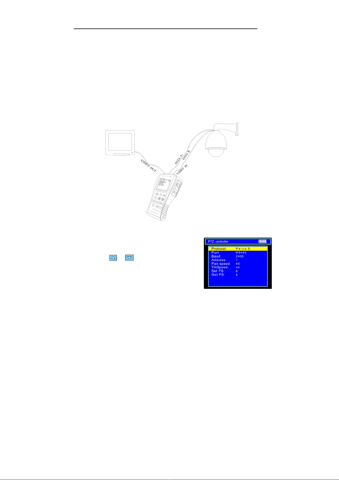
3.2 PTZ Controller
Display the input video images. Pan/tilt the P/T unit and zoom in/ out the image. Setup the
controlling parameters like protocol, communication port, baud rate, PTZ ID, pan/tilt speed;
set and call preset position.
The following connections should be confirmed before use
a. The Video In interface of the Test-CCTV28 and the output interface of camera
b. Data A+ of the Test-CCTV28 and A+ of the PTZ camera or controlling device, data B- of
the instrument and B- of the PTZ camera or controlling device
Note: Don’t connect communications interface with a circuit the voltage higher than 6V.
a. Press SET key to enter the sub-menu of PTZ controller.
b. Press the or key to select the parameter
which we want to change the value.
c. Press ENTER key to save the change or press RETURN
key to give up the change
d. Press SET key to exit the sub-menu.
e. Press POWER key to full-screen the image
A. Protocol: Select the protocol according to the protocol of the PTZ camera. Up to 21
Tabla de contenidos
Manuales populares de Equipo de prueba de otras marcas

SMART
SMART KANAAD SBT XTREME 3G Series Manual de usuario

Agilent Technologies
Agilent Technologies BERT Serial Manual de usuario

Agilent Technologies
Agilent Technologies N3280A Manual de usuario

Vernier
Vernier Go Direct Voltage Manual de usuario

Lifeloc
Lifeloc R.A.D.A.R. Manual de usuario

Fluke
Fluke T5-600 Instrucciones de funcionamiento e instalación


