G&F Manufacturing Gulfstream Guía de inicio rápido

G & F Manufacturing
Swimming Pool Heat
Pump
Owner’s
Installation & Operations Manual
5005001B
Version 2.02

Page 2
TABLE OF CONTENTS
Introduction 3
Installation 5
Location 5
Wind Tie Down 5
Water Plumbing 6
Electrical Hook Up 6
Bonding 7
Water Chemistry Maintenance 8
Heat Pump Features 9
Heat Pump Operation 10
Control On/Off 10
Pool/Spa Modes 10
Changing Set Point Temperature 11
Heater Running Time 11
Keypad Lockout 11
Defrost Cycle 11
Condensate Draining 11
Care & Maintenance 12
Cleaning 12
Winterizing 12
Troubleshooting 13
Service 15

Page 3
INTRODUCTION
Congratulations on purchasing the most advanced high efficiency,
microprocessor-controlled pool and spa heat pump available. Your heater
has been manufactured with the most state-of-the-art quality control
equipment available today to ensure the highest quality product delivered to
your door. A heat pump pool heater is a highly efficient, cost effective
method of pool heating. Proper operation and care will result in many years
of swimming enjoyment and pleasure.
Your new pool heater is a self-contained unit designed specifically for
swimming pool and spa heating. It utilizes the sun’s free energy by
extracting heat from the sun-warmed air and transferring it efficiently to the
pool water. Because your pool heater moves the free heat from the
outside air to the pool, rather than create heat, as a fossil fuel or electric
resistance heater does, it can heat your swimming pool or spa for up to
80% less cost than these other less efficient methods.
As with all pool heating methods, you are advised to utilize a pool cover at
night and when the pool is not in use. The pool cover should be used if the
night temperature is 15°F (8°C) less than the desired pool temperature.
This will keep evaporation, the greatest source of heat loss, to a minimum,
greatly reducing the overall pool heating costs. During warmer weather,
the pool cover may not be required.
Your pool and spa heater combines simplicity with trouble-free
performance. As with most appliances, an understanding of proper
operation of the heater is important. Proper installation and operation
increases efficiency and reduces heating costs. Your pool heater is
designed with features that make it simple to operate, maintain and service.
Proper installation enhances these features and minimizes problems. This
manual will provide you with the information needed to properly install,
operate and maintain your heater.

Page 4
Please be sure to complete and mail in the Warranty Registration Card that
is provided in the package with your heater. This card helps us to notify
you about new information on your heater.

Also, please take a moment and jot down the following information. If you
should ever need to call us for service or a question, we will need this
information:
Model Number:___________________________________
Serial Number:___________________________________
Purchase Date:___________________________________
Dealer Name/Address/Phone #:_______________________
__________________________________________________

Page 5
INSTALLATION
LOCATION
The unit is designed for outdoor installation and shall not be placed in a
totally enclosed area such as a shed or a garage unless ventilation is
provided to ensure adequate air exchange for proper operation.
Recirculation of cold discharge air back into the evaporator coil will greatly
reduce heating capacity and efficiency of the unit and void the compressor
warranty.
The heater should be located as close as practical to the existing pool pump
and filter to minimize water piping length. The use of 90°bends and short
radius elbows in the water piping should be limited to keep water pressure
drop to a minimum.
Your heater features an up-flow fan for quiet operation. Air is pulled
through the evaporator coil and discharged through the top grill. At least 4
feet clearance should be allowed above the unit for unrestricted air
discharge. The unit must not be installed under a porch. Any side of the
unit should be located at least 12 inches from a wall or other obstruction for
unrestricted air intake and service access.
Mount the unit on a flat, level surface, preferably a concrete or fabricated
slab. The unit should be completely isolated from the building foundation or
wall to prevent the possibility of sound or vibration transmission into the
building. The base of the unit may be used to fasten to if local codes
require securing the unit to the slab.
Make sure that there are no sprinkler heads near or directly spraying into
the heater. Cap off or redirect heads as needed.
WIND TIE DOWNS
The unit can be strapped down using the Gulfstream strap kit. Attach a
strap to each side and anchor to the deck.

Page 6
WATER PLUMBING
The piping sequence: pool pump / filter / heater / Chlorinator / Pool. In-line
chlorinators must be down stream of the heater to minimize harm to the
pool equipment. Rigid PVC piping is recommended and all joints should be
secured with PVC glue. Make sure that the direction of the water flow
through the heater is correct as indicated by the labels on the unit. When
the piping installation is complete, operate the pool pump and check the
system for leaks. Check the filter pressure gauge to ensure that excessive
pump head pressure is not indicated.
The recommended flow rate is 50 gpm through the heater.
For questions on multiple heater installations, please contact our
engineering department. Multiple unit installations should always be in
parallel circuits.
ELECTRICAL HOOK UP
CAUTION: The main power disconnect must be off before opening the
access panel.
It is recommended that the wiring of your heater be done by a qualified
electrician in accordance with local code requirements.
IMPORTANT: The electrical conduit
must
be run up through the base of
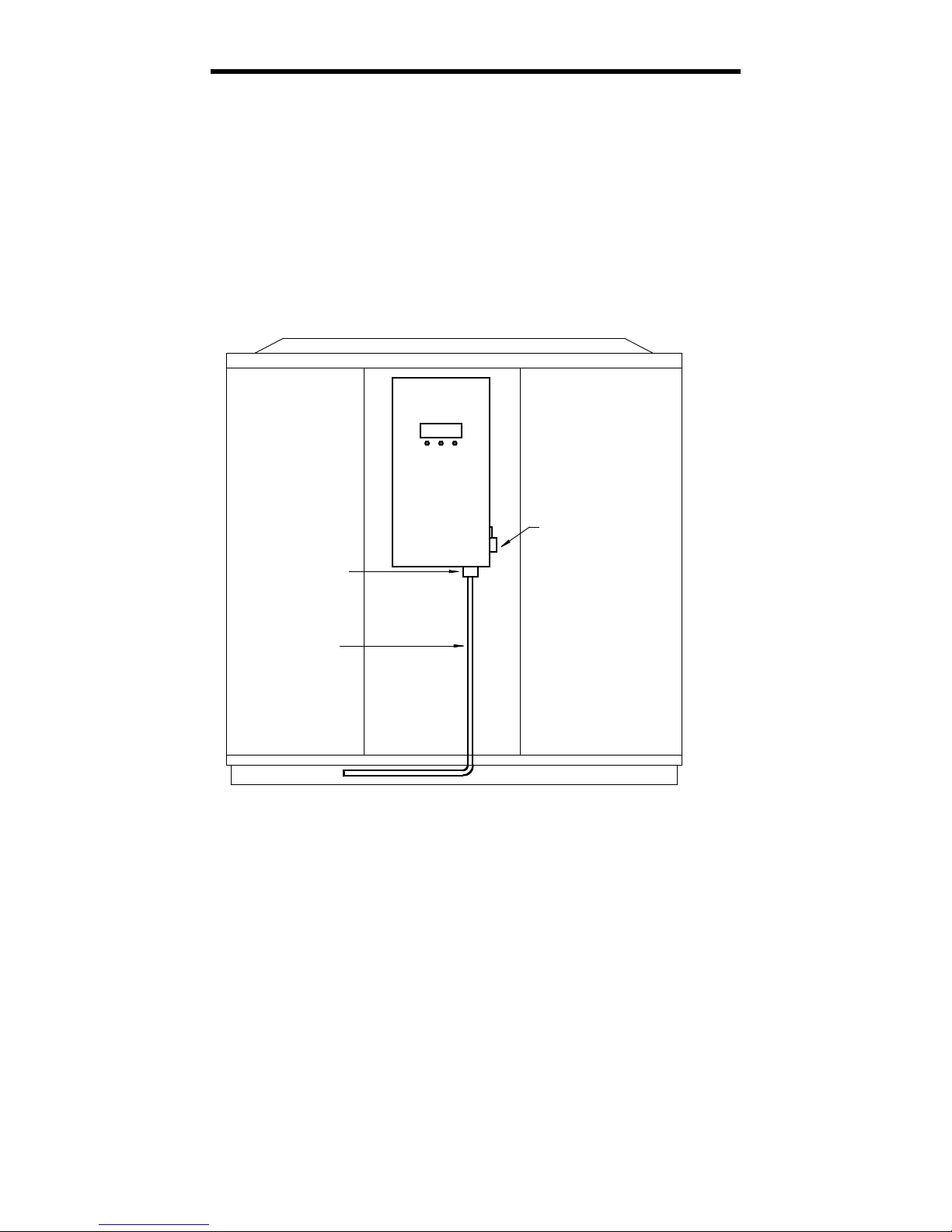
the unit and connected at the control box with a conduit connector.
A properly sized breaker and copper wire must be used. See inside access
panel for wiring diagram.

Page 7
BONDING
Because all metals have different electrical potentials, ALL metal
and electrical components of the pool system must be bonded
together. This includes the metal framework of the pool, lights, pump,
filter, heater, any automatic chlorine generator and any other metal or
electrical equipment. On some older pools, this substructure bond wire may
not exist. In this case, a 6 to 8 ft. copper rod must be driven into the
ground near the pool equipment and all electrical and metal components
must be bonded to the rod. A bonding lug is furnished on the side of the
control box of the heater for the bond wire to be attached. Warranty will
be void if system is not properly bonded.
Attach Bond Wire From
Pool Pump Here
Control
Box
Approved Connector
To Main Power
Flexible Conduit

Page 8
WATER CHEMISTRY MAINTENANCE
Not only is the water chemistry of your pool or spa important to the health
of you and your family, it also directly affects the life of your heater. This is

the most important item in the maintenance of the heater. If the water
chemistry is improperly maintained or if the chemicals are improperly
introduced into the water, this will damage the heater’s internal heat
exchanger and could eventually cause a leak, rendering the heater
inoperable.
CAUTION: Damage to the heater due to improper water chemistry
is not covered under the warranty.*
Following is the table for essential water quality readings, which must be
constantly maintained:
Description
Normal Range
Verify
PH Level
7.4 to 7.8
1 time per week
Chlorine Concentration
1.0 to 3 PPM
1 time every 2 to 3 days
Total Alkalinity
80 to 120 PPM
1 time every 2 to 3 weeks
Total Dissolved Solids
Below 2400 PPM
1 time per month
Calcium Hardness
200 to 300 PPM
1 time per month
The location of the chemicals’ introduction to your system is also critical to
the heater’s life. If an automatic in-line chlorinator or brominator is used, it
must be located downstream of the heater. A trap must also be installed
between the chlorinator and the heater to prevent chlorine return into the
heater.
IMPORTANT: Never leave any type of solid chlorine in the pool skimmer.
This will cause a high concentration of Chlorine to enter the heater, causing
premature corrosion. You must divert water flow directly to the pool before
adding fast dissolving chemicals in skimmer.
*Models with Titanium Tube heat exchangers do not have a water
chemistry exclusion in their warranty.

Page 9
HEAT PUMP FEATURES
CABINET – Your heat pump’s cabinet is made from a maintenance-free,
rust-free plastic that is UV resistant. It will last for years and any dirt or
dust may simply be wiped away with a cloth or sprayed off with a water
hose. The use of a product such as Armor- All will restore its natural luster.
DO NOT USE CLEANERS THAT CONTAIN ALCOHOL.
CONTROL – State-of-the-art LCD readout control. Displays mode and
temperature of the water for ease of operation. No programming to learn.
Dual thermostats allow user to set pool and spa temperatures. The control
is self-diagnostic and will display a fault if there is a problem. Other
features include: lockout, spa timer, automatic low temperature defrost and
remote control capabilities.
ULTRA-QUIET – The unit is equipped with a low RPM fan motor in
combination with a deep drawn venturi to ensure whisper quiet operation.
HIGH EFFICIENCY – The heat pump utilizes the latest in compressor
technology to produce the highest efficiency available when coupled with
the over-sized enhanced fin evaporator coil.
EASE OF INSTALLATION - The unit is equipped with easy-to-install,
hand-tightened unions for a quick and trouble-free installation. The unions
will accept 2” PVC piping. The electrical connection is made with one entry
directly into the control box for a quick hook-up and a neat appearance.
EASY ACCESS – The heater was designed for quick and easy access for
installation and diagnosis. The service panel is removed with two screws
and access to all service connections is right up front and easy to reach.
This allows the installation and service to be done quickly and efficiently –
so valuable time is not wasted.

Page 10
HEAT PUMP OPERATION
CONTROL ON/OFF
When the unit is powered up, but in the OFF mode, the display will show
“OFF”. To turn the unit on, press the Up arrow button until desired
temperature is reached. To turn the unit off press and hold the Down arrow
button until the display shows off. This point will be one level below 50
degrees. This is convenient for shutting the unit down for short periods of
time.
CAUTION: When the control is in the “OFF” mode, there is still high
voltage to the unit. If you want to turn the unit off for long periods of time,
shut the main power off to the unit at the main or service disconnect.
POOL/SPA MODES
The control is equipped with two independent thermostats, one for pool
temperature and one for spa temperature. This is to allow the user to
preset a temperature of their choice and switch between the two settings
with the POOL/SPA button located on the control. When power is applied to
the control it will turn on in the previous mode, whether it is Pool Heat or
Spa Heat. When water is flowing through the unit and the water
temperature meets the specified set point condition, the control will initiate
a heat cycle.
If you do not have a spa, you can use the spa thermostat as a second
temperature setting if you do not want to maintain full temperature all the
time. For instance, if you swim on the weekends only, you can set the
temperature back during the week to save costs but maintain a warmer
temperature for a shorter recovery time for the weekend.
ATTENTION: There is a 5-minute time delay upon completion of a heating
cycle. This is to ensure that the critical components do not fail due to short
cycling of the heater.
The display on the control will show the thermostat being used and the
operating mode on the top line and the current water temperature on the
bottom line. The possible mode displays are: “POOL – HEAT”, “SPA –
HEAT”.
Tabla de contenidos
Otros manuales de Bomba de calor de G&F Manufacturing
Manuales populares de Bomba de calor de otras marcas

Mitsubishi Electric
Mitsubishi Electric PUZ-SWM60VAA Manual de usuario

Dimplex
Dimplex LI 16I-TUR Guía del usuario

Carrier
Carrier WSHP Open v3 Guía de configuración rápida

TGM
TGM CTV14CN018A Manual de usuario

Carrier
Carrier 38MGQ Series Manual de usuario

Kokido
Kokido K2O K880BX/EU Guía de solución de problemas

Viessmann
Viessmann VITOCAL 300-G PRO Type BW 2150 Guía rápida

Carrier
Carrier 48EZN Manual de usuario

Viessmann
Viessmann KWT Vitocal 350-G Pro Series Instrucciones de funcionamiento

Ariston
Ariston NIMBUS Manual de usuario

Weishaupt
Weishaupt WWP L 7 Guía del usuario

GE
GE Zoneline AZ85H09EAC Manual de usuario