Galebreaker Bayscreen Manual de usuario
Bayscreen®
Installation and Operating
Instructions
ENG
To watch video scan
QR code with phone
camera

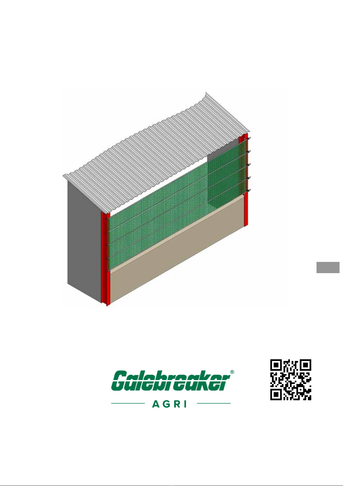
Bayscreen® Introduction
-2-
Figure 1, System Overview and Individual Components

Bayscreen® Introduction
-3-
ENG
INTRODUCTION
Parts List
Reference: Quantity/Height Product Description
1.0m 1.5m 2.0m 3.0m
A
1 1 1 1 1 Ba
y
screen Sheet
B1 4 6 8 12 Plastic Edge Protector (50cm long)
C1 3 4 5 7 50mm Cranked Hook
(
L>10m
)
C2 3 4 5 7 25mm Cranked Hook
(
L<10m
)
D1 3 4 5 7
50mm Ratchet Hook (L>10m)
D2 3 4 5 7 25mm Ratchet Hook
(
L<10m
)
E1 3 4 5 750mm Ratchet
(
L>10m
)
E2 3 4 5 725mm Ratchet
(
6.5m<L<10m
)
E3 3 4 5 725mm Ratchet
(
L<6.5m
)
F1 3 4 5 7
M12x130 Bolt and nyloc nut
F2 12 16 20 28 Ratchet Spacer L = Screen Length (m)
Additional Top Support
Bayscreens over 15m wide are supplied with an additional central support.
Figure 2, Additional Top Support

Bayscreen® Introduction
-4-
ENG
Reference Qty Product Description
G1 1 50mm Ratchet Bracket
H1 1 50mm Ratchet
I1 1 4m x 50mm Webbin
g
J1 4 85mm x 85mm Clamp Plate
K1 1 M12 x 90 Bolt, nut
L1 3 M8 x 40 Bolt, nut, washer *
M1 8 M8 x 20 Bolt, nut, washe
r
* Alternative M8 fastenings required if fixing to wood or concrete
Your Safety
The installation of the screen is not recommended at excessive wind speeds as it
could cause damage to the curtain or injury to the Installer.
Items Required By The Installer
Standard tool kit including:
Sharp pair of scissors or knife
Electric drill (L>15m)
Key Instructions
ATTENTION: Observe the given instructions otherwise the product or adjacent
items may be damaged
NOTE: Helpful comments and information to assist in installation or use of your
product
Fixing Variations
NOTE: Before starting the installation it is advisable to read
these instructions completely to help understand the general
procedure and options available. Keep the instructions supplied
for reference purposes.
NOTE: Colour versions of the installation instructions can be
downloaded from our website:
www.galebreaker.com

Bayscreen® Introduction
-5-
ENG
The following are alternative fixing methods for installations to buildings where the
building columns are of H-Beam construction but opposite orientation, or manufactured
from timber or concrete.
Figure 3, Fixing Variations
Steel angle on concrete upright
Steel angle on H-Beam, external
Steel angle on H-Beam, internal
Steel angle on timber upright
Steel plate on concrete upright

Bayscreen® Installation
-6-
ENG
INSTALLATION
1. Check the contents of your Bayscreen against the parts list using Figure 1. Do
not let the screen material come into contact with any sharp objects or edges.
2. Fix plastic protectors (B1) over the inner edges of the pillars (Figure 4). If you are
unable to use these protectors due to the building design then it is important
sharp objects and rough surfaces are covered with PVC strip or similar.
Figure 4, Plastic Edge Protector
ATTENTION: Failure to fit these protectors will reduce the life of
your Bayscreen.
NOTE: For standard installation the ratchets are on the right-
hand side and the webbing faces outwards.

Bayscreen® Installation
-7-
ENG
3. Fix the plain hooks (C1 or C2) into the screen loops (A1) and attach to left-hand
H-Beam, Figure 5(i).
4. Offer up the screen (A1) to the opening. Screens must be connected from pillar
to pillar, under no circumstances must they pass intermediate pillars or
obstructions.
5. If necessary trim the screen to the required length. For best results, use sharp
scissors / knife with a straight edge to remove the fabric either side of the
webbing strap ensuring all corners have a radius. Always remove surplus fabric,
do not just cut either side of the webbing that allows a loose flap, to be generated,
Figure 5(ii).
Figure 5, Fitting the Sheet
ATTENTION: Cut with care, do not cut through horizontal
webbing, and do not peel or remove the fabric off the back of the
webbing.

Bayscreen® Installation
-8-
ENG
6.1 If L>10m assemble ratchet hooks (D1) to ratchets (E1) using the M12x130 bolts
and nuts (F1) with two ratchet spacers (F2) each side of the ratchet, Figure 6a.
Figure 6a, 50mm Hook and Ratchet Assembly
6.2 If L<10m clip the 25mm ratchet hook (D2) to the 25mm ratchet (E2 or E3) as in
Figure 6b.
Figure 6b, 25mm Hook and Ratchet Assembly

Bayscreen
®
Installation
-9-
ENG
7. Hold the ratchet assembly in position on opposite H-Beam. Thread the top strap
through the ratchet, do not fully tension screen at this stage, Figure 5(iii). Repeat
stage on all remaining ratchets/straps. Push all the ratchets and hooks away from
each other to provide good tension to the vertical edges of the Bayscreen (Figure
7).
Figure 7, Tensioning the Screen
8. Tighten all ratchets as firmly as possible, applying the tension equally to avoid
wrinkles appearing in the material. Tension can be applied as firmly as possible
by hand to the point where operation of the ratchet is no longer possible, but
ATTENTION: Under no circumstances allow the Galebreaker
mesh material to run into the ratchet. Further trimming may be
necessary.

Bayscreen® Installation
-10-
ENG
under no circumstances use levers to add more tension. Should the hooks slide
on the pillars then a preventative ‘stop’ should be fastened to the building upright.
ATTENTION: Tension ratchets fully, lack of tension will cause
damage to the Bayscreen. Only tension by hand, use of levers
could cause damage to the ratchets.
ATTENTION: To ensure the ratchet functions correctly there must
be a minimum of 150mm webbing (for 50mm ratchet) or 100mm
webbing (25mm ratchet) around the ratchet barrel for secure &
permanent tensioning of the screen.
ATTENTION: Overloading the ratchet barrel with webbing will
restrict the tension you can apply to the screen due to an
increase in friction and a decrease in leverage. To free surplus
webbing pull ratchet release catch on handle and open 180
degrees until ratchet body is flat and pull on webbing strap.
Mounting Screens in Series
9. When screens are installed in series they share a common pillar, the ratchet of
one screen can be set above or below the hook of the other screen creating an
offset. Alternatively they can be installed ‘in line’ as detailed in Figure 8(i)
(25mm webbing) and in Figure 8(ii) (50mm webbing).
10. Install screens working from right to left as viewed from the side with the
webbing. When fitting the second screen, offer up the ratchet hook (D1 or D2)
to straddle the webbing of the previous screen and cut two slits in the fabric 4cm
long to coincide with the legs of the hook. Cut the material 1cm back past the
edge of the upright so that the hook contacts on the upright and does not put
load onto the fabric. Pass the ratchet hook through the slits and onto the
upright, then tension the screen as previously instructed.
Tabla de contenidos
Manuales populares de Maquinaria agrícola de otras marcas

GSi
GSi PNEG-2314 Manual de usuario

Checchi & Magli
Checchi & Magli TEXDRIVE Manual de usuario

Amazone
Amazone Cenius 4003-2TX Manual de usuario

MASSEY FERGUSON
MASSEY FERGUSON MF 9313S Manual de usuario

Cima
Cima BLITZ Instrucciones de funcionamiento y mantenimiento

Amazone
Amazone CombiDisc 3000 Instrucciones de instalación


