Fuji Electric EconoPIM M721 Guía del usuario

© Fuji Electric Co., Ltd. All rights reserved.MT5F22233b
Mounting Instruction
Oct. 2022
EconoPIMTM and EconoPACKTM are registered trademark of Infineon Technologies AG, Germany.
Fuji Industrial IGBT Module
Press Fit Type
EconoPIMTM (M721, M722)
EconoPACKTM (M647, M648, M1202)

MT5F22233b © Fuji Electric Co., Ltd. All rights reserved.
CONTENTS
1
1. Scope of application 2
2. Mounting the module to printed circuit board 4
2-
1.
Requirements for printed circuit board
4
2-
2.
Notes when mounting components on a printed circuit board
5
2-
3.
The press
-in and press-out process of printed circuit board
6
2-
4.
Soldering the module to the printed circuit board after press
-out
10
2-
5.
Screw tightening to printed circuit board
11
4. Warning 25
3. Mounting to heat sink 21
3-
1.
Surface conditions of heat sink
21
3-
2.
Application of thermal grease
22
3-
3.
Screw tightening the module to heat sink
23
3-
4.
Fixing the printed circuit board to heat sink
24
5. Storage and transportation notes 26
6. Stencil mask drawing 27

MT5F22233b
1. Scope of application
© Fuji Electric Co., Ltd. All rights reserved. 2
Fig.1 Terminal shape before and after the press-in process to the printed circuit board
(b) Terminal shape after the press-in process(a) Terminal shape before the press-in process
PCB PCB
EconoPIMTM and EconoPACKTM are registered trademark of Infineon Technologies AG, Germany.
This document describes how to safely mount and use press fit type of EconoPIMTM and
EconoPACKTM products for the following part numbers shown in Table 1.
Press fit type : Products that can be mounted solder less to printed circuit board (PCB)
Press fit terminals have the characteristic shape shown in Fig.1(a). When the press fit terminal is
pressed into the PCB, contact pressure is applied from both sides of the terminals, and they were
deformed and inserted as shown in Fig.1(b). The deformation pressure makes it possible to mount the
product on the PCB solderless.
When handling the product, in addition to the contents described in this document, please check the
Warning and Caution in the product specification too.
MT5F22233b © Fuji Electric Co., Ltd. All rights reserved. 3
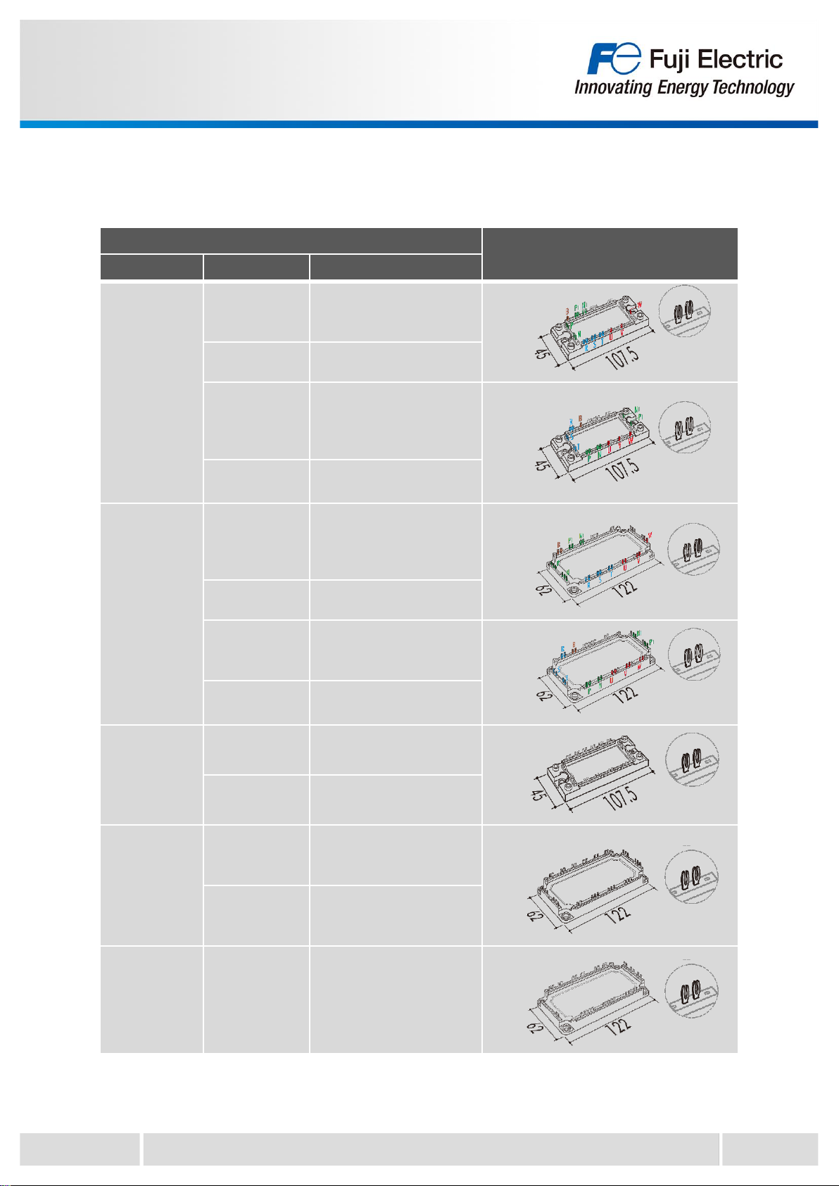
Applicable model Package outlines
Package name Series Part number
M721
X series 7MBRxxxXWA065-xx
7MBRxxxXWA120-xx
7MBRxxxXWE120-xx
V series 7MBRxxxVW120-xx
X series
7MBRxxxXYA065-xx
7MBRxxxXYE065-xx
7MBRxxxXYA120-xx
7MBRxxxXYE120-xx
V series 7MBRxxxVY060-xx
7MBRxxxVY120-xx
M722
X series 7MBRxxxXXA065-xx
7MBRxxxXXA120-xx
7MBRxxxXXE120-xx
V series 7MBRxxxVX120-xx
X series 7MBRxxxXZA065-xx
7MBRxxxXZA120-xx
7MBRxxxXZE120-xx
V series 7MBRxxxVZ060-xx
7MBRxxxVZ120-xx
M647
X series 6MBIxxxXWE120-xx
V series 6MBIxxxVW-060-xx
6MBIxxxVW-120-xx
M648
X series 6MBIxxxXXA120-xx
6MBIxxxXXE120-xx
6MBIxxxXRXE120-xx
V series 6MBIxxxVX-060-xx
6MBIxxxVX-120-xx
6MBIxxxVX-170-xx
M1202 V series 12MBIxxxVX-120-xx
Table 1 Scope of application of this mounting instruction
The target part numbers of this mounting instruction are as follows.

MT5F22233b
2. Mounting the module to printed circuit board
4
© Fuji Electric Co., Ltd. All rights reserved.
Table 2 Requirements for a printed circuit board
Min. Typ. Max.
Drill hole diameter - 2.35mm -
Through hole diameter 2.14mm 2.20mm 2.29mm
Cu thickness in hole 25μm - -
Electrolytic tin plating thickness - - 15μm
Cu thickness of conductors 35μm 70um, 105μm -
PCB thickness 1.6mm 2.0mm -
PCB material FR4
Fig.2 Recommended specification of a printed circuit board
(b) Holes for mounting the module(lower tool)(a) PCB cross section and each dimension
Example) for M722
2-1. Requirements for printed circuit board
Table 2 and Fig.2 show the recommended specifications of a printed circuit board (PCB).
The recommended specifications in Table 2 is evaluated based on IEC60352-5. When using a PCB
other than the recommended specifications, evaluation is required.
< Requirements for the PCB material >
Double-sided PCB in accordance with IEC 60249-2-4 or IEC 60249-2-5.
Multilayer PCB in accordance with IEC 60249-2-11 or IEC 60249-2-12.
For example, the through hole diameter should be in the range of 2.14mm to 2.29mm with properly
Sn/Cu plated sidewall. If the diameter is too small, problems such as damage to the terminals and
PCBs may occur during the press-in process. On the other hand, if the diameter is too large, a gap
will be created between the terminal and the PCB, causing problems such as vibration and shock,
resulting in reduced reliability.
In addition when mounting the module to the heatsink after mounting the PCB, holes for module
mounting are required on the PCB. (Fig. 2 (b)) These holes for mounting can be used as a guide pin
hole for the module fixing tool when inserting the module into the PCB.
Press fit terminal
Through hole diameter
PCBPCB
PCB thickness
Drill hole diameter Electrolytic tin plating
thickness
Cu thickness in hole
Cu thickness of
conductors
Electrolytic tin plating (tip)
Cu alloy + Ni plating
Holes for mounting the module to heat sink

MT5F22233b © Fuji Electric Co., Ltd. All rights reserved.
2-2. Notes when mounting components on a printed circuit board
For press fit products, it is recommended that components be mounted in an area at least 5mm
away from the center of the press-fit terminals because the PCB near the press-fit terminals may be
deformed during the press-in process. Also, design the press-in/press-out tool to be used in such a
way that it does not affect the components.
5
MT5F22233b
2-3. The press-in and press-out process of printed circuit board
This section describes the procedure of the press-in and press-out process of PCB.
Table 3 shows the recommended press speed and load (average per terminal) during the press-in
and press-out process for the minimum and maximum PCB through-hole diameters.
If the press-in force is too low, there will be issues with the contact between PCB and the module
terminals. On the other hand, if the press-in force is too high, it can damage the PCB and other
mounted components.
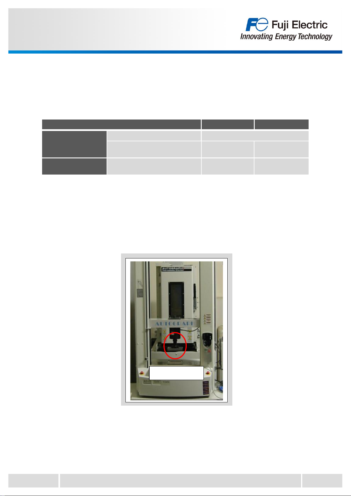
Therefore, it is recommended to use dedicated machine and tools for the press-in and press-out
process. Fig.3 shows a photo of the press machine (example).
© Fuji Electric Co., Ltd. All rights reserved. 6
Fig.3 Example of press machine
Module installation
position
Through hole diameter of PCB 2.14mm(Min.) 2.29mm(Max.)
Press-in process Recommended press speed 25mm/min
Recommended load
(Average load per terminal) Typ. 93N Typ. 74N
Press-out process Recommended load
(Average load per terminal) Typ. 45N Typ. 49N
Table 3 Recommended press speed and load

MT5F22233b © Fuji Electric Co., Ltd. All rights reserved.
2-3-1. Press-in / press-out tool
During press-in/press-out of the PCB, use a tool for press-in/press-out to ensure that the press-fit
terminals and through holes are not misaligned. Examples of a press-in tool is shown in Fig.4 and a
press-out tool is shown in Fig.5.(example for M722 and M648)
Please refer to the appendix for the actual tool dimensions.
During the press-in process, pass the lower tool guide pins through the hole for the guide pins of the
PCB.
In the example of Fig.4, the module mounting holes are used as guide pin holes.
7
Fig.4 Recommended press-in tool
Fig.5 Recommended press-out tool
Upper tool
Lower tool
Upper tool
Lower tool
Upper tool
Lower tool
Lower tool
Guide pins
Upper tool

MT5F22233b © Fuji Electric Co., Ltd. All rights reserved. 8
Fig.6 Example of press-in process
(a) Set the press-in upper tool and lower tool on
the press machine.
(b) Set the PCB by aligning the PCB hole for
the guide pins with the guide pins of the
lower tool.
(d) Press the module with the recommended
speed and load.
(c) Set the module by aligning the terminals of
the module with the through holes of the
PCB.
2-3-2. Example of press-in process
Fig.6(a)-(d) show the example of press-in process.
Please refer to section 2-3 for the recommended speed and load.

MT5F22233b © Fuji Electric Co., Ltd. All rights reserved. 9
Fig.7 Example of press-out process
(a) Set the press-out upper tool and lower tool
on the press machine. (b) Set the PCB mounted module on the lower
tool.
(d) The module is removed from the PCB and
drops onto the lower tool.
(c) Press the terminals of the module with the
upper tool.
2-3-3. Example of press-out process
Fig.7(a)-(d) show the example of press-out process.
Please refer to section 2-3 for the recommended load.
Este manual sirve para los siguientes modelos
4
Tabla de contenidos
Otros manuales de Equipos industriales de Fuji Electric


