FSK Rhino 232 Manual de usuario


CONTENTS
Getting Started ..................................................................................................................................... 4
Overview ...................................................................................................................................................................................................
Installation ..............................................................................................................................................................................................
Programming ........................................................................................................................................................................................
Rhino 232 Panel Overview ............................................................................................................. 5
Installation ...............................................................................................................................................
Mounting of the alarm panel .......................................................................................................................................................
Wiring the alarm panel ....................................................................................................................................................................
Power supply ..........................................................................................................................................................................................
Piezo Buzzers .........................................................................................................................................................................................
Sound bomb ..........................................................................................................................................................................................
Strobe lamp ............................................................................................................................................................................................
Wired zones ............................................................................................................................................................................................
Wiring .........................................................................................................................................................................................................
Wireless zones .......................................................................................................................................................................................
Programming .........................................................................................................................................
Entering the programming mode ............................................................................................................................................
Navigating the programming menus .....................................................................................................................................
Setting up zones ..................................................................................................................................................................................
Programming wireless zones ......................................................................................................................................................
Users ............................................................................................................................................................................................................
Area Options ..........................................................................................................................................................................................
Hardware options ...............................................................................................................................................................................
Keypad Options ...................................................................................................................................................................................
Outputs .....................................................................................................................................................................................................
Communications ................................................................................................................................................................................
Upload/Download (UDL) ................................................................................................................
Using the UDL ......................................................................................................................................................................................
Appendix A .............................................................................................................................................
Text Entry Mode ..................................................................................................................................................................................
Hex Entry Mode ...................................................................................................................................................................................
Warranty Information .......................................................................................................................
4
4
4
6
6
6
7
7
7
7
7
7
8
12
12
12
13
14
15
17
18
20
21
22
Zone Commissioning Process ..................................................................................................... 24
29
29
32
32
32
33

The Rhino 232 panel is a wireless alarm panel
The Rhino 232 panel is equipped with an onboard GSM modem which sends alarms to the
control room
The Rhino 232 panel works with the MiRhino mobile application which allows the user to
remotely control and monitor his or her alarm system
The Rhino 232 panel has been designed with ease-of-use, ease of installation and ease of
programming in mind
GETTING STARTED
1. Overview
2. Installation
Connect battery to the panel
Mount the panel in a location that has good GSM signal reception and that’s convenient
for the user
Wire the power supply to the alarm panel
Mount the sensors
Program the alarm panel
Perform the commissioning process
3. Programming
The keypad
The UDL (up/download) software supplied on the FSK DVD. The UDL programming can be
done locally via a USB connection or remotely via the FSK Gateway
The Rhino 232 alarm panel can be programmed via the following means:
4 Rhino 232 Installation Manual |

P O W E R STAT US TROUBLE
23
4 5 6
7 8 9
CLEAR 0ENTER CHIME
BYPASS
STAY
ARM
i
1P
The Rhino 232 panel Wireless Devices
Bi-Directional
Raptor Remote Gate Module
Indoor PIR Door Contact Third Party
PIR Interface
Optional
Power Supply
USB Port for
Programming
PC for Local
Upload/Download
OR
Remote Upload/Download
via the internet
Smart Phone Apps
RHINO 232 PANEL OVERVIEW
12V Strobe
(< 50mA)
12V Sound
Bomb
(< 200mA)
Piezo buzzers
Back view of panel
Rhino 232 Installation Manual 5 |

-+
Power Supply
Optional
12V Sound
Bomb
Optional
12V Strobe
5V FROM
POWER
SUPPLY
ZONE 2
ZONE 1
AUX
12V
5V
GND
SRN -+
STRB
Z1
Z2
COM
(≤ 200mA)
(≤ 50mA)
INSTALLATION
The alarm panel should be mounted in a location that has good GSM signal strength and that
is convenient for the user such as the living room or bedroom.
The alarm panel should be mounted away from metal objects as this will negatively affect the
performance of the wireless transceiver and GSM module.
Make sure the internal battery is plugged in as leaving it unplugged will negatively affect the
performance of the wireless transceiver and GSM module.
Mounting the alarm panel
Once the location has been chosen, remove the panel from the its bracket and mount the bracket
to the wall.
Use four 5mm screws and wall plugs to mount the bracket.
Tighten the screws until the bracket is firmly in place, but do
not over-tighten them.
Wiring the alarm panel
6 Rhino 232 Installation Manual |

Power Supply
Use only the 5V power supply with the alarm panel. A higher voltage supply or AC supply will
damage the alarm panel.
Connect the positive lead of the power supply to the positive terminal (5V) of the wall bracket
and the negative lead of the power supply to the negative terminal (GND) of the wall bracket.
Use a good quality security cable to do the connection like a ripcord cable.
NB. Please make sure to plug in the battery that is inside of the alarm panel.
Sound Bomb
The sound bomb may not draw more than 200mA.
Do not connect a conventional siren.
The alarm panel can drive an optional 12V sound bomb which can be used as an internal or
external siren.
NB:
Strobe Lamp
The alarm panel can drive an optional 12V strobe lamp.
Note: The strobe lamp must be a low current variet as it will shorten the y (not more than 50mA)
internal battery standby time.
Wired Zones
Up to two wired zones can be connected to the alarm panel (in addition to the wireless zones). The
wiring options for the zones are shown are in the next section. The auxillary 12V power supply can
be used to power up to two wired PIRs.
Note: Power supplied to the PIRs will shorten the internal battery stand-by time.
Wiring
Alarm Alarm
Normally Closed
Detector
Alarm
Normally Open
Detector
Normally Closed
Detector
with EOL
3K3
Piezo Buzzers
The alarm panel has two built-in piezo electric buzzers which sound whenever there is an alarm.
NB: These buzzers will only sound if one of the wired outputs is programmed as a siren/bell.
Rhino 232 Installation Manual 7 |

The detector contact is normally closed and opens when there is an alarm.
Program the zone wiring property to normally closed
NORMALLY CLOSED DETECTOR
The detector contact is normally open and closes when there is an alarm.
Program the zone wiring property to normally open
NORMALLY OPEN DETECTOR
The detector has a normally closed contact. The EOL resistor is used to detect that there is a
fault condition on the wire to the sensor.
Program the zone wiring property to single EOL-N/C
SINGLE END-OF-LINE (EOL) NORMALLY CLOSED
Wireless Zones
The wireless door contact has a reed switch which is used in conjunction with a magnet to sense if
a door is opened. In addition, there is an alternative of a zone input terminal.
Refer to the door contact leaflet.
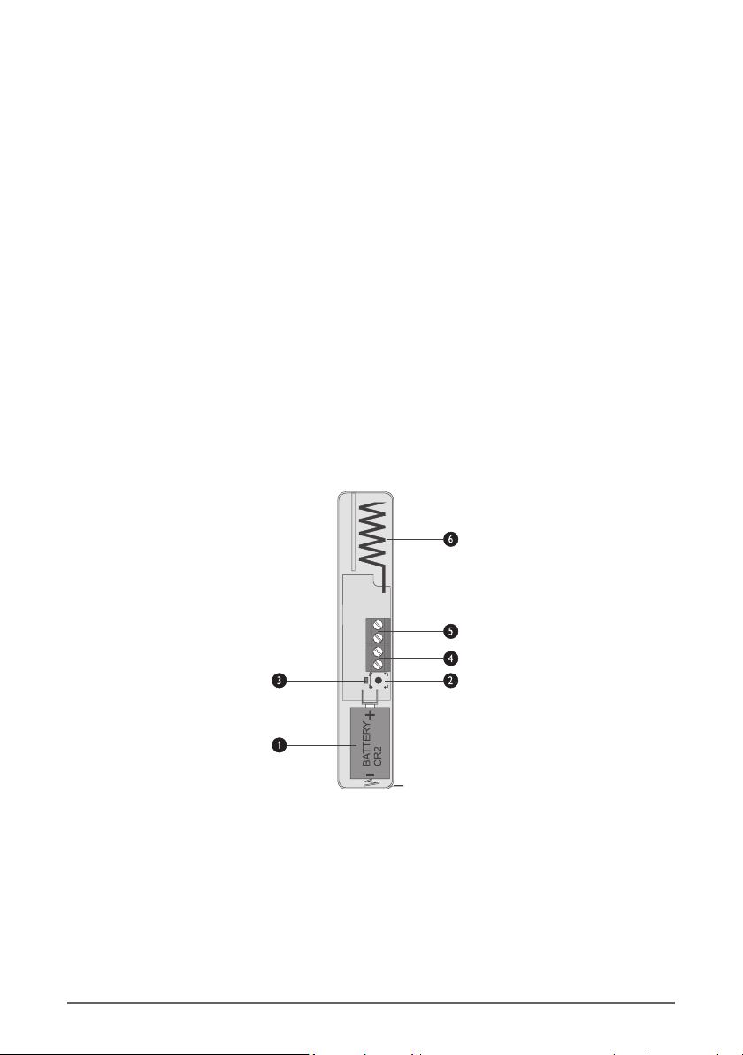
RH-100 Wireless Door Contact
Use a CR2 3V Li-ion battery. Observe the polarity.
1. BATTERY
The tamper switch is used to detect the removal of the lid. It is also used for programming the
device into the panel.
2. TAMPER SWITCH
The LED lights when the device is sending a signal to the alarm panel.
3. ACTIVITY LED
8 Rhino 232 Installation Manual |
#I SecureGuard Installaon Manual
The wireless door contact has two detector inputs. The first is the reed switch which is activated
by the magnet. The second requires a voltage-free normally closed contact to be wired into the
terminals. Both inputs report back to the same zone on the control panel. If the zone is not used,
it should be shorted out with a link.
4. ZONE INPUT TERMINALS
The magnetic reed switch detects the presence of the magnet fitted to the door. There is a
marking on the door contact which indicates where the magnet should be centred. The magnet
should be mounted within 15mm of the door contact (when the door is closed).
5. MAGNETIC REED SWITCH
The antenna is used for transmitting the wireless signal.
NB. Avoid mounting the door contact on or near a metal frame as this will negatively affect
communications with the alarm panel.
6. ANTENNA
The RH-101 is engineered to be fitted to third party PIR wireless-ready detectors. It has a normally
closed alarm input as well as a normally closed tamper input.
Refer to the in-box leaflet.
RH-101 Wireless 3rd Party Interface
Use a CR123A 3V Li-ion battery. Observe the polarity.
1. BATTERY
The tamper switch is used to detect the removal of the lid. It is also used for programming the
device into the panel. The tamper switch of a third-party PIR wireless-ready detector is used in
conjunction with the tamper terminal (5).
2. TAMPER SWITCH
The LED lights when the device is sending a signal to the alarm panel.
3. ACTIVITY LED
Rhino 232 Installation Manual 9 |

The normally closed contacts from the PIR are connected to these terminals. An alarm will be
sent when the PIR opens its contact.
4. ALARM INPUT TERMINAL
The normally closed tamper output from the PIR is connected to these terminals.
5. TAMPER INPUT TERMINAL
The antenna is used for transmitting the wireless signal.
NB. Avoid mounting the unit on or near a metal frame as this will negatively affect
communications with the alarm panel.
6. ANTENNA
The RH-200 indoor PIR has built-in wireless for direct communication to the Rhino 232 panel. The
PIR is allocated to one of the available wireless zones.
Refer to the in-box leaflet.
RH-200 Wireless Indoor Passive
Use a CR123A 3V Li-ion battery. Observe polarity (the
positive terminal is marked).
1. BATTERY
The tamper switch detects that the lid has been opened. It
is also used for learning the device into the panel.
2. TAMPER SWITCH
The LED illuminates when movement is detected.
3. ACTIVITY LED
The Raptor gate module has been specifically designed for controlling gate motors, garage doors,
etc. It has an output that can open and close a gate (control). Its input cannot be assigned to a
zone on the Rhino 232 panel.
Refer to the in-box leaflet.
Raptor Bidirectional Gate Module
5
4
5
3
2
1
If this jumper is on, the sensitivity is normal. If it is off, the
sensitivity is high.
4. SENSITIVITY JUMPER
If this jumper is on, the LED is enabled. If it is off, the LED is
disabled.
5. LED JUMPER
10 Rhino 232 Installation Manual |
Tabla de contenidos
Otros manuales de Panel de control de FSK


