Forcefield DUALGIZER DG1 Instrucciones de instalación

Installation & Operation Instructions
SAVE THESE INSTRUCTIONS
AC/DC Dual Power
Electric Fence Energiser
AC
DC
MODE DISPLAY
Adapter or Battery Input
OUTPUT
DISPLAY
NAVI-BUTTON
MOUNTING
HOLES

Blank page

READ BEFORE YOU INSTALL YOUR ELECTRIC FENCE ENERGISER Page 1
● Only use this electric fence energiser for the purpose
indicated in this manual.
● RISK OF ELECTRIC SHOCK! To reduce the risk of
electric shock do not open the energiser. Refer to
trained service personnel or service centre.
● Always turn off energiser before handling.
● Never modify the design of an energiser.
● Avoid contacting electric fence wires especially with
the head, neck or torso.
● Do not climb over, through or under a multi-wire
electric fence. Use a gate or a specially designed
crossing point.
● The appliance is not to be used by persons (including
children of 8 years old and below) with reduced
physical, sensory or mental capabilities, or lack of
experience and knowledge, unless they have been
given supervision or instruction in the use of the
appliance in a safe way and understand the hazards
involved.
● Children shall not play with the appliance.
● Cleaning and user maintenance shall not be made by
children without supervision.
● DO NOT install where children, elderly or unhealthy
persons may come in contact with the live portions of
electric fencing. Use electric fence warning signs
where humans may come in contact with the fence.
WARNINGS
READ ALL INSTRUCTIONS BEFORE
INSTALLATION AND USE.

READ BEFORE YOU INSTALL YOUR ELECTRIC FENCE ENERGISER Page 2
● Any part of an electric animal fence that is installed
along a public road or pathway shall be identified at
frequent intervals by warning signs securely fastened
to the fence posts or firmly clamped to the fence wires.
~ The size of the warning sign shall be at least
100 mm × 200 mm.
~ The background colour of both sides of the warning
sign shall be yellow.
~ The inscription on the sign shall be black and shall
be either:
– the symbol of Figure 1, or
– the substance of the wording:
“CAUTION: Electric fence”.
~ The inscription shall be indelible, inscribed on both
sides of the warning sign and have a height of at
least 25 mm.
● Barbed wire or razor wire shall not be electrified by an
energiser. A non-electrified fence incorporating barbed
wire or razor wire may be used to support one or more
off-set electrified wires of an electric animal fence.
The supporting devices for the electrified wires shall
be constructed so as to ensure that these wires are
positioned at a minimum distance of 150mm from the
vertical plane of the non-electrified wires. Barbed wire
and razor wire shall be earthed at regular intervals.
Figure 1

READ BEFORE YOU INSTALL YOUR ELECTRIC FENCE ENERGISER Page 3
● DO NOT connect simultaneously to a fence and any other device such as a cattle
trainer or poultry trainer. Otherwise, lightening striking your fence will be conducted
to all other devices.
● An electric animal fence shall not be supplied from two separate energisers or from
independent fence circuits of the same energiser. For any two separate electric
animal fences, each is to be supplied from a separate energiser, independently
timed. The distance between the wires of the two electric animal fences shall be at
least 2.5meters. If this gap is to be closed, this shall be effected by means of
electrically non-conductive material or an isolated metal barrier.
● In areas prone to brush fires, turn off fence energiser on very dry days.
● During lightning storms do not disconnect wires or approach the electric fence.
● Follow the earthing recommendations in this manual. A distance of at least 10m
shall be maintained between the energiser’s ground electrode and any other
ground/earthing system connected parts such as the power supply system
protective earth or the telecommunication system earth.
● Connecting leads that are run underground shall be run in conduit of insulating
material or else insulated high voltage cable shall be used.
● Care must be taken to avoid damage to the connecting leads due to the effects of
animal hooves or tractor tires sinking into the ground.
● Connecting leads shall not be installed in the same conduit as the mains supply
wiring, communication cables or data cables.
● Connecting leads and electric animal fence wires shall not cross above overhead
power or communication lines.
Crossings with overhead power lines shall be avoided wherever possible. If such
a crossing cannot be avoided it shall be made underneath the power line and as
nearly as possible at right angles to it. If connecting leads and electric animal
fence wires are installed near an overhead power line, the clearances shall
not be less than those shown in table below:
Power Line Voltage
V
Clearance Dist.
m
≤ 1000V 3m
>1000 and ≤ 33000V 4m
> 33000V 8m
● If connecting leads and electric animal fence wires are installed near an overhead
power line, their height above the ground shall not exceed 3m. This height
applies to either side of the orthogonal projection of the outermost conductors of
the power line on the ground surface, for a distance of:
• 2 m for power lines operating at a nominal voltage not exceeding 1000 V;
• 15 m for power lines operating at a nominal voltage exceeding 1000 V.

● Electric animal fences intended for deterring birds, household pet containment or
training animals such as cows need only be supplied from low output energisers
to obtain satisfactory and safe performance.
● In electric animal fences intended for deterring birds from roosting on buildings,
no electric fence wire shall be connected to the energiser earth electrode.
A warning sign shall be fitted to every point where persons may gain ready
access to the conductors.
● Where an electric animal fence crosses a public pathway, a non-electrified gate
shall be incorporated in the electric animal fence at that point or a crossing by
means of stiles shall be provided. At any such crossing, the adjacent electrified
wires shall carry warning signs.
● DO NOT operate electric fence energisers near any combustible materials
including gasoline, cleaning fluids or kerosene.
● Follow all national, state and local codes and regulations that apply to installation
of an electric fence in your area.
● Electric fences are very effective psychological barriers when properly installed
and when animals are trained to the fence. Electric fences are NOT complete
physical barriers. Erratic animal behavior cannot be predicted and occasional
fence penetration can occur. Therefore, the manufacturer assumes no liability for
animal containment, injury or the consequences for the misuse of the equipment.
Note:
The fence live (hot) terminal is indicated by a red knob and a lightning bolt
symbol ( ). The ground is indicated by a black knob and an arrow symbol ( ).
READ BEFORE YOU INSTALL YOUR ELECTRIC FENCE ENERGISER Page 4
PRODUCT SPECIFICATIONS & FEATURES
● 100-240V AC input with AC-DC power adapter.
● External 12V rechargeable battery input - BATTERY NOT INCLUDED.
● Full-Power and Half-Power modes – User selectable.
● Fence Voltage Indicators – LED indicators let you know the fence voltage, and if
your fence has too much leakage.
● Battery Voltage Indicators – LED indicators notify when to swap you current
battery with a fully charged battery.
● 1J, 3J or 5J output energy dependent on the model chosen
(not stored energy, but output to fence).
● Secure mounting with 3 mounting holes on the top of the unit and 2 at bottom.
● IP44 ingress protection.
● ABS casing with UV stabilisation.

KEYS TO SUCCESSFUL ENERGISER INSTALLATION Page 5
Take care of the 5 following recommendations:
1. Grounding - Carefully install a complete ground system. Most electric fence
failures are caused by an improper ground system (see Diagram 1).
2. Connections – Carefully connect lead out wire, ground wire and fence line
splices. This is the second most common cause of electric fence failure.
Use clamps, split bolts and taps for securing wire connections. Make sure all
connection surfaces are of bare, shiny metal
(see Diagram 2: Wire Splice and Connections).
3. Wire - Use adequately insulated hook-up wire (rated for at least 20,000V) where
the live / “hot” wire must travel underground. Never use standard household
insulated wire, which is typically rated for only 600 volts or less.
4. Isolation - Maintain at least 25m from buried and above ground utility company
ground rods, water pipes, metal sidings, telephone wire and stock watering tanks.
5. Training - Finally, it is very important that an animal's first experience with an
electric fence shock is one of respect. Some animals require more than one
shock experience for lasting respect of the fence line. Always train the animal to
the fence prior to unsupervised entry into pastures by insuring that the animal's
first approach to the fence is slow, without stress and that an effective repelling
shock is experienced.
Tools Needed
1. Hammer or Screwdriver – for mounting energiser
2. Wire cutters/strippers – to cut and strip insulation
3. Post driver – to install ground rods and posts
4. Digital kilovolt meter – for electric fence testing and troubleshooting.
Accessories Needed
1. 1 to 3 galvanised ground rods – minimum 1.5 to 1.8m long, >12mm in diameter.
2. 1-3 ground rod clamps.
3. Insulated underground hook-up wire – 10m (20,000V rating).
4. Line clamps.
5. Highly Recommended: One lightning choke and a lightning diverter or a
combination choke and diverter. Lightning is the number one cause of failure in
electric fence energisers. Use these to protect the your energiser.
6. Nails or screws for mounting the energiser.

ENERGISER INSTALLATION (Steps 1-6) Page 6
Step 1: Mount The Energiser
Using the energiser's 3 upper mounting keyholes and the 2 lower mounting holes,
drive either screws or nails into a wall or stable wooden surface to securely mount
the energiser. Not all energiser mounting holes are needed, but use as many as
possible to ensure the energiser is stable and will not move if the fence or power
wires are pulled.
Wall Mounting
Mains Power
Socket
screws
x3
1. Unscrew the black fence terminal knob ( ) on the right and remove it together
with the top washer.
2. Make a “J” shape in a bare end of hook-up wire,
unless the wire is too stiff, then use it straight.
3. Hook this bare end of wire over the terminal bolt
or lay the straight wire up into the top recess.
4. Replace the top washer and the black knob and
hand tighten.
Do not use pliers or other tools to over tighten
the knob or you may damage it.
10 to 14 gauge insulated lead-out wire
(rated 20,000V) is commonly used for this.
5. Properly connect the other end of the wire to
your ground rod(s).
“J” shape
or straight
Black
Step 2: Connect energiser’s ground terminal to your ground rod(s)
Red
screws
x2
ENERGISER INSTALLATION continued. Page 7
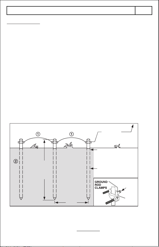
Diagram 1: Ground System Installation
1. 12-14 gauge galvanised wire.
2. Ground rods: 1.5 - 1.8m long (1.8m preferred) long by ½” (or more)
in diameter galvanised steel rods.
1.8m top
to bottom
3.0m
Min. 25m from utility ground,
underground wire and pipes,
water tanks and phone lines
Min. 10m from building
foundation and metal siding
To Energiser:
Use 10 to 14 gauge
insulated 20,000V wire
Damp Earth
Thread wire
through hole,
tighten screw
IMPORTANT
Avoid pounding your ground rods
into SANDY, DRY and ROCKY soil
The “ground system” consists of 1 or more highly conductive ground rods driven into
the soil and then connected by wire to the ground terminal of your fence energiser.
The ground system allows current to flow through the soil to complete the circuit
needed for delivering an effective shock.
1. Locate an area of soil for ground rods that contains good conductive earth
(not sandy or rocky). Soil that is moist throughout the year is best. The ground
system should be located within 25m of your fence energiser and at least 10m
away from buildings.
2. Locate a ground system a minimum of 25m away from: Utility company (electric,
gas, water) ground system, underground water pipe, metal water tanks, and
a minimum of 10m from metal siding on buildings.
3. Drive one 1.5 - 1.8m (1.8m preferred) >12mm in diameter galvanised ground
rod into the ground. Leave 10cm above the ground for securing ground clamps.
Mark the area as a hazard.
4. If more than 1 ground rod is used, connect the ground rods in a series, 3m apart,
with one piece of continuous 10 to 14 gauge galvanised wire. Use clamps to
secure the wire to the ground rods. The ground hook-up wire should be equal to
or larger than the diameter of the fence line wire.
Step 2 continued:

ENERGISER INSTALLATION continued. Page 8
Step 3: Connect the fence live (hot) terminal
“J” shape
or straight
CAUTION
DO NOT use pliers or other mechanical
means to tighten the terminal knobs
or they may be over-tightened and damaged.
Red
Note: Ensure the energiser is OFF before making this connection or you may receive
a shock.
1. Unscrew the red fence terminal knob ( ) and remove it together with the top
washer.
2. Make a “J” shape in a bare end of hook-up wire, unless the wire is too stiff, then
use it straight.
3. Hook this bare end of wire over the terminal bolt or lay the straight wire up into the
top recess.
4. Replace the top washer and the red knob and hand tighten.
10 to 14 gauge insulated lead-out wire
(rated 20,000V) is commonly used for this.
5. Properly connect the other end of the wire
to your fence. See step 4.
Refer to Diagram 2 on following page:
WIRE SPLICING AND CONNECTIONS.
Connect the Black terminal
( ) to the Ground rod
using the Black lead.
Connect the Red terminal
( ) to the Fence line using
the Red lead.
Ground rod
Live Fence Wire
Live Fence Wire
Live Fence Wire
Step 4: Connect to the fence
Mark the top
of the ground
rod as a hazard
Este manual sirve para los siguientes modelos
2
Otros manuales de Fuente de alimentación de Forcefield


