
FLUVO Mushroom Manual de usuario

Mushroom
Operator’s Manual
27109 - B
GB
Translation of the original

2
Mushroom
Version: 27109-B
Schmalenberger GmbH + Co. KG
D-72072 Tübingen / Germany
Table of contents
1 General information.......................................................................... 3
2 Proper use ......................................................................................... 3
3 Safety instructions............................................................................ 3
4 Description of the device ................................................................. 3
5 Technical data ................................................................................... 4
6 Pump circuit ...................................................................................... 5
7 General description .......................................................................... 6
8 Mushroom.......................................................................................... 6
8.1 Shuttering for water supply 90°/ concrete tile pool......................................................... 6
8.2 Installation process for 90°water supply / concrete tile pool ......................................... 7
8.3 Shuttering for vertical water supply/
concrete tile pool............................................................................................................. 8
8.4 Installation process for vertical water supply / concrete tile pool .................................... 9
8.5 Shuttering for vertical water supply/
concrete liner pool......................................................................................................... 10
8.6 Installation process for vertical water supply / concrete liner pool ................................ 11
8.7 Shuttering for vertical water supply/
concrete pool with brush-applied sealant...................................................................... 12
8.8 Installation process for vertical water supply/
concrete pool with brush-applied sealant...................................................................... 13
8.9 Installation process for vertical water supply/ subsequent installation.......................... 14
9 Spare parts Mushroom ................................................................... 15
9.1 Concrete tile pool / 90°water supply ............................................................................ 15
9.2 Concrete tile pool / vertical water supply ...................................................................... 16
9.3 Concrete liner pool / vertical water supply .................................................................... 17
9.4 Concrete pool with brush-applied sealant / vertical water supply ................................. 18
9.5 Subsequent installation / vertical water supply ............................................................. 19

OPERATOR’S MANUAL
3
Mushroom
Version: 27109 - B
Schmalenberger GmbH + Co. KG
D-72072 Tübingen / Germany
1 General information
This mushroom represents the state of the art. It has been manufactured with the greatest
care and is subject to continuous quality control.
This Operator’s Manual contains important information to ensure the mushroom is
operated safely, properly, and economically. Your strict observance is necessary to
prevent dangers and ensure a long service life for the mushroom.
This Operator’s Manual does not take into consideration local requirements. The operator
is responsible for ensuring these requirements are met, including personnel retained to
assemble the system.
2 Proper use
The mushroom was developed for use in public swimming pools. It can be used in both
indoor and outdoor pools.
The entire system or parts of it are not suitable for use in other systems.
Accordingly we explicitly instruct you only to use such parts or the entire system for their
intended purpose.
The mushroom must not be operated beyond the values specified in the technical data
(section 5). If you have any questions, please contact your Customer Service
representative or the manufacturer.
3 Safety instructions
Please read this Operating Manual carefully before installing the mushroom and placing it
in operation. Make certain you have understood everything.
The operator must ensure that
• the Operator’s Manual is always available for operating personnel
• the instructions in the Operator’s Manual are observed
• the mushroom is stopped immediately if any abnormal electrical voltages,
temperatures, noises, vibrations, leaks, or other faults occur.
4 Description of the device
fluvo offers various mushrooms as swimming pool attractions. They are a valuable and
attractive addition to any public pool. Pool-side parts are made of stainless steel and pool
installation parts are made of bronze and PVC.

OPERATOR’S MANUAL
4
Mushroom
Version: 27109 - B
Schmalenberger GmbH + Co. KG
D-72072 Tübingen / Germany
5 Technical data
Connection DN 125 (PVC)
Material Installation housing - 2.1096 / PVC (concrete tile pool or
concrete pool with brush-applied
sealant; also for subsequent
installation
- 1.4571 (concrete liner pool)
Fixing elements 1.4401 / 1.4571
Assembly kit 1.4571 (all types of pools)
Usage limits 1.4401 (max. 3000 mg/l Cl
-)
1.4571 (max. 4500 mg/l Cl
-)
Operating pressure 0.4 - 0.6 bar
Max. perm. pressure 0.8 bar
Curtain diameter Ø 1500 mm Ø 1800 mm Ø 2300 mm
Flow rate 90 m
3
/h 120 m
3
/h 150 m
3
/h

OPERATOR’S MANUAL
5
Mushroom
Version: 27109 - B
Schmalenberger GmbH + Co. KG
D-72072 Tübingen / Germany
6 Pump circuit
Fig. 1
P1 Centrifugal pump
P2 Suction DN 100
P3 Suction-end shut-off unit
P4 Pipeline
P5 Mushroom
P6 Pressure-end shut-off unit
a ø1500 mm / ø 1800 mm / ø 2300 mm
b 2200 mm
c ø 256 mm
The centrifugal pump (P1) is non-self priming and must therefore be installed below the
pool water level. The water is drawn out of the pool through the suction connection (P2).
The intake quantity can be adjusted through the pressure-end shut-off unit (P6).
The suction-end shut-off unit (P3) must always be completely open while the system is in
operation. Water is directed through the pipe system (P4) to the mushroom (P5). An
additional shut-off unit (P6) is built into the pipe system (P4) for individual control of the flow
rate.
The water flows through the mushroom (P5) back into the swimming pool. The mushroom
can be started either by an air button located directly in the pool or from a control panel
outside the pool.

OPERATOR’S MANUAL
6
Mushroom
Version: 27109 - B
Schmalenberger GmbH + Co. KG
D-72072 Tübingen / Germany
7 General description
The fluvo mushroom consists of an installation kit, an assembly kit and a fluvo standard
pump.
fluvo mushrooms are available in 3 different curtain sizes (a= ø 1500 mm, ø1800 mm, ø
2300 mm) and for 4 different types of pools. The stand pipe height up to the bottom edge
of the umbrella isc= 2200 mm for all sizes.
All parts in contact with media are designed for water quality according to DIN 19643.
8 Mushroom
8.1 Shuttering for water supply 90°/ concrete tile pool
Fasten the installation kit (01) onto the inside form wall (W) with the locking screws (02),
nuts (03) and distance washers (04).
Always fasten the installation kit (01) onto the reinforcement with the binding wire in
addition.
Before the concrete is brought in, the installation kit (01) must be installed to correct
dimensions and securely fastened so it cannot be moved between the form walls.
Note!
For curtain diameters of 1800 mm and 2300 mm, two DN 100 suction units
are required.
Note!
Make certain the installation kit (01) is resting fully against the form wall (W).
Fig. 2
Before loosening the form wall (W), the
fastening parts that are no longer needed
(02, 03, 04) and the protective cap (H)
must be removed.
H Protective cap
W Form wall
01 Installation kit
02 Locking screws
03 Nut
04 Distance washer
d= DN 125

OPERATOR’S MANUAL
7
Mushroom
Version: 27109 - B
Schmalenberger GmbH + Co. KG
D-72072 Tübingen / Germany
8.2 Installation process for 90°water supply / concrete tile pool
Apply a layer of mortar (M) and tiles (F) almost up to the hold ring (I).
Fasten the stand pipe with foot flange (07) onto the installation kit (01) with hex. socket
head cap screws (08) and distance washers (09).
Pull the screen (12) over the stand pipe (07).
Place the screen (10) on the stand pipe (07) and adjust it so that the holes in the screen
(10) and those in the stand pipe (07) line up.
Fasten with counter-sunk screws (11).
Fig. 3
F Tiles
I Hold ring
M Mortar
01 Installation kit
07 Stand pipe with foot flange
08 Hex. socket head cap screw
09 Distance washer
10 Screen
11 Counter-sunk screw
12 Screen
d= DN 125
Fig. 4
Important:
Before placing the screen (10) on the
stand pipe (07), seal both pipes with
DIRKO sealant.

OPERATOR’S MANUAL
8
Mushroom
Version: 27109 - B
Schmalenberger GmbH + Co. KG
D-72072 Tübingen / Germany
8.3 Shuttering for vertical water supply/
concrete tile pool
Fasten the installation kit (05) onto the form wall (W) with the locking screws (02), nuts (03)
and distance washers (04).
Always fasten the installation kit (05) onto the reinforcement with the binding wire in
addition.
Before the concrete is brought in, the installation kit (05) must be installed to correct
dimensions and securely fastened so it cannot be moved between the form walls.
Before loosening the form wall (W), the fastening parts that are no longer needed (02, 03,
04) and the protective cap (H) must be removed.
Note!
Make certain the installation kit (05) is resting fully against the form wall (W).
Fig. 5
H Protective cap
W Form wall
02 Locking screws
03 Nut
04 Distance washer
05 Installation kit
d= DN 125

OPERATOR’S MANUAL
9
Mushroom
Version: 27109 - B
Schmalenberger GmbH + Co. KG
D-72072 Tübingen / Germany
8.4 Installation process for vertical water supply / concrete tile pool
Apply a layer of mortar (M) and tiles (F) almost up to the hold ring (I).
Fasten the stand pipe with foot flange (07) onto the installation kit (05) with hex. socket
head cap screws (08) and distance washers (09).
Pull the screen (12) over the stand pipe (07).
Place the screen (10) on the stand pipe (07) and adjust it so that the holes in the screen
(10) and those in the stand pipe (07) line up.
Fasten with counter-sunk screws (11).
Fig. 6
F Tiles
I Hold ring
M Mortar
05 Installation kit
07 Stand pipe with foot flange
08 Hex. socket head cap screw
09 Distance washer
10 Screen
12 Screen
d= DN 125
Fig. 7
Important:
Before placing the screen (10) on the
stand pipe (07), seal both pipes with
DIRKO sealant.
OPERATOR’S MANUAL
10
Mushroom
Version: 27109 - B
Schmalenberger GmbH + Co. KG
D-72072 Tübingen / Germany
8.5 Shuttering for vertical water supply/
concrete liner pool
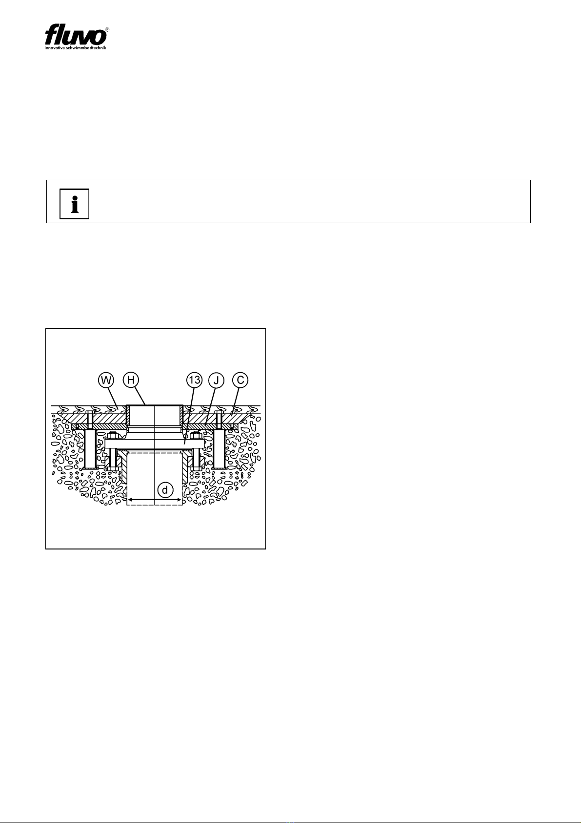
Nail the installation kit (13) with fitting (C) securely onto the form wall (W).
Always fasten the installation kit (13) onto the reinforcement with the binding wire in
addition.
Before the concrete is brought in, the installation kit (13) must be installed to correct
dimensions and securely fastened so it cannot be moved between the form walls.
Before loosening the form wall (W), the nails that are no longer needed and the protective
cap (H) must be removed.
Then remove the fitting (C) from the installation kit (13).
Note!
Make certain the installation kit (13) is resting fully against the form wall (W).
Fig. 8
C Fitting
H Protective cap
W Form wall
13 Installation kit
d= DN 125
Tabla de contenidos
Otros manuales de Equipo de iluminación de FLUVO


Manuales populares de Equipo de iluminación de otras marcas


Qazqa
Qazqa Suplux SL 3 Black 103062 Manual de usuario

Commercial Electric
Commercial Electric 54568141 Manual de usuario

CREE LIGHTING
CREE LIGHTING 304 Series Manual de usuario

Goobay
Goobay 49867 Manual de usuario

ECOMAN ITALIA
ECOMAN ITALIA LED T8 Manual de usuario

Alkalite
Alkalite Krypton KT-81 Manual de usuario


