
Flowserve 682-53B System Manual de usuario
Experience In Motion
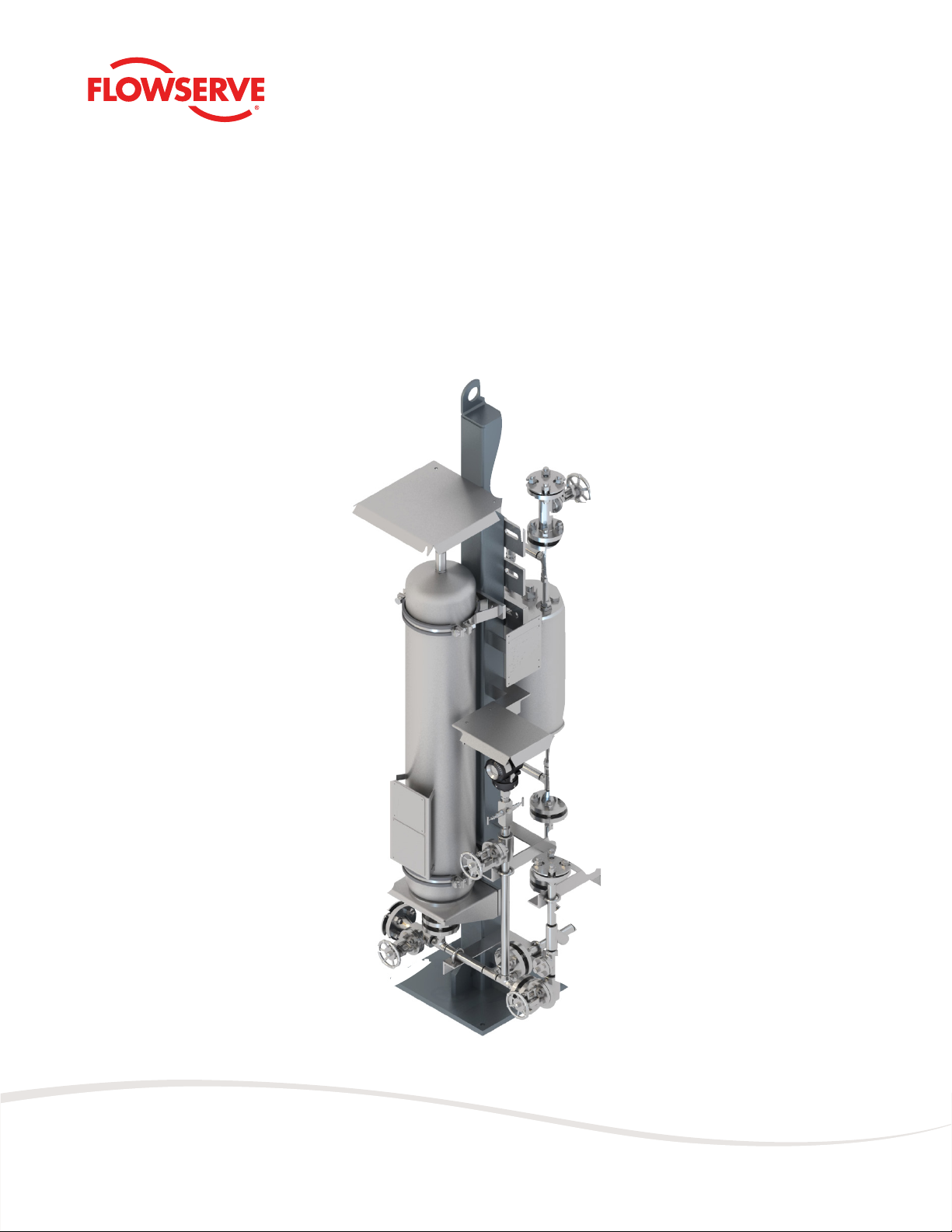
682-53B System
USER INSTRUCTIONS
Installation
Operation
Maintenance

Flowserve.com 2SSIOM000742-00 (EN/AQ) November 2022
682-53B System
CONTENTS
1 Introduction 3
1.1 About this manual 3
1.2 How to use this manual 3
1.3 Other supplied documentation 3
1.4 Conformity with norms and directives 3
1.5 Use of alerts and icons 4
2 Safety 5
2.1 682-53B hazards 5
2.2 General safety 5
2.3 Trained and qualied personnel 5
2.4 Personal protective equipment (PPE) 6
3 Environmental Considerations 7
3.1 Disposing of waste products 7
3.2 End-of-life equipment 7
4 Design Overview 8
4.1 Purpose of 682-53B 8
4.2 Typical 682-53B installations 8
4.3 P & ID 9
4.4 Parts 10
4.5 Theory of operation (typical system) 12
4.6 Identifying the product (nameplate) 12
4.7 682-53B Product offerings 12
5 Transport and Storage Requirements 13
6 Installation 14
6.1 Introduction 14
6.2 Installation requirements 14
6.2.1 Safety considerations 14
6.2.2 System seal cooler mounting height 15
6.2.3 Interconnecting pipes 15
6.3 Installation procedure 15
7 Operation 18
7.1 Set up system 18
7.2 Start up system 19
7.3 Monitor system 19
7.4 Shut down system 20
8 Maintenance 21
8.1 Introduction 21
8.2 Periodic maintenance tables 21
8.3 Check barrier uid pressure 21
8.4 Rell barrier uid 22
8.5 Change barrier uid 22
8.6 Check accumulator pressure 23
8.7 Charge accumulator 24
9 Troubleshooting 26
10 Spare Parts 27
11 Appendix 28
11.1 System logbook 28
11.2 GA drawings 29
11.3 Vendor documentation 30
Copyright
Copyright Flowserve © November 2022. Published by Flowserve.
This manual contains regulations and drawings of a technical
nature. No part of this document may be reproduced or
distributed by any means, or used for competitive purposes,
without the written consent of the publisher
All information (including illustrations) in this manual is subject
to change without prior notice. Flowserve does not accept any
liability for any instance of damage or malfunction through
non-adherence to these instructions.

Flowserve.com 3SSIOM000742-00 (EN/AQ) November 2022
682-53B System
1 Introduction
1.1 About this manual
This manual (which is intended for operating,
maintenance, and supervisory personnel) provides
information on installing, operating, and maintaining the
682-53B system.
NOTE: As hazardous conditions can result from planned
as well as unforeseen circumstances, pressurized
equipment shall always be operated with caution.
Before installation, equipment should always be fully
inspected including, but not limited to checking for:
• Any possible damage due to transport or storage
• Cleanliness, required before operation
• Existence of an afxed nameplate with correct
inspection markings and design/test conditions
clearly annotated
1.2 How to use this manual
Only trained and qualied personnel should use this
manual. Refer to section 2.3. Inexperienced personnel
should only work on this system under the supervision of
a qualied person.
Before using this manual, make sure you have fully read
and understood the safety section. If you are new to
the system, pay particular attention to section 4, which
describes the system in detail.
When maintaining the system, always make sure you
follow the maintenance procedures. Pay particular
attention to the alerts and icons.
1.3 Other supplied documentation
The appendix contains the General Arrangement
drawings (called GA drawings) and documentation on the
vendor parts. The instructions in this manual sometimes
refer to the vendor documentation. If a reference is
made to the vendor documentation, you must follow the
instructions in that documentation as well.
1.4 Conformity with norms and directives
The 682-53B system conforms to the following norms
and directives (if applicable):
• Machine directive/2006/42/EC
• NEN 5509:2016
• ATEX Directive 2014/34/EU
• PED 2014/68/EU
• ASME B31.3
• ASME BPVC Section VIII Div. 1
• API Standard 682

Flowserve.com 4SSIOM000742-00 (EN/AQ) November 2022
682-53B System
1.5 Use of alerts and icons
This manual uses “Notes”, “Cautions”, “Warnings”, and
“Dangers” to alert you of important information and
dangerous situations. These alerts (from the least severe
to the most severe) are:
NOTE: “Notes” inform you of important additional
information.
aCAUTION: The equipment, product or surrounding
area can be damaged if the “caution” is not obeyed.
úWARNING: Personnel can be (seriously) injured, or
the equipment can be seriously damaged if the
“warning” is not obeyed.
c DANGER: Personnel can be seriously injured
(resulting in death) if the “danger” is not obeyed.
c DANGER/WARNING: Dangers or Warnings that refer
to the use of the system in potentially explosive
atmosphere – in accordance with the ATEX
Directive 2014/34/EU.
The above icons are the general icons that are used for
“Cautions”, “Warnings”, and “Dangers”. More specic
icons are also used, depending on the type of hazard.
Refer to the following example:
úWARNING – HIGH PRESSURE: The accumulator can
burst if it is over pressurized. Fill the accumulator
slowly; check the pressure gauge regularly.
STOP
STOP

Flowserve.com 5SSIOM000742-00 (EN/AQ) November 2022
682-53B System
2 Safety
2.1 682-53B hazards
The following hazards can be present in the 682-53B
system:
• High pressure
• Explosion
• Dangerous chemicals/media
• Temperature (hot surfaces)
• Nitrogen (N2) in the accumulator
• Dangerous moving parts (during installation)
If the 682-53B system has any external leaks, you must
stop the system immediately and have the leak repaired
by qualied personnel.
2.2 General safety
When installing, operating and maintaining the system,
pay particular attention to safety:
• Obey all applicable safety laws and regulations.
• Obey all plant regulations.
• Make sure that only trained and qualied personnel
work on the system. Refer to section 2.3.
• Read and understand each part of this manual.
• Follow the installation, maintenance and operating
procedures exactly.
• Wear the relevant personal protective equipment (PPE).
Refer to section 2.4.
• Never work alone.
• Make sure that adequate safety equipment is installed
in and around the work area: rst aid kits, safety
showers (if applicable), re extinguishers, escape
routes, shut-off valves, etc.
• Make sure that personnel are fully trained on how to
use the safety equipment. A qualied rst aid specialist
must always be available for each shift.
• Read the plant requirements for handling hazardous
materials.
• Check MSDS for relevant information.
2.3 Trained and qualified personnel
Qualied personnel are people who have been authorized
by those responsible for the safety of the Plant to perform
the necessary work, and who can recognize and avoid
possible dangers. The following aspects determine the
qualication of personnel:
• Appropriate training
• Relevant experience
• Knowledge of relevant standards and specications
• Knowledge of accident prevention regulations
• Knowledge of plant regulations and operating conditions

Flowserve.com 6SSIOM000742-00 (EN/AQ) November 2022
682-53B System
2.4 Personal protective equipment (PPE)
The 682-53B is often used for applications containing
high-pressure, dangerous and/or toxic chemicals. When
operating or maintaining this system, make sure you wear
the appropriate PPE: protective clothing, gloves, safety
glasses, etc.
Always follow local regulations regarding PPE.
If one (or more) of the below icons is shown in the work
place, the equipment must be worn at all time.
When operating outside, PPE to be worn to prevent slip,
trip and/or fall.

Flowserve.com 7SSIOM000742-00 (EN/AQ) November 2022
682-53B System
3 Environmental Considerations
aCAUTION: You are required by law to dispose
of waste products and end of life equipment,
according to local regulations.
3.1 Disposing of waste products
Any waste products resulting from the use or maintenance
of the 682-53B must be disposed of according to local
environment laws and regulations.
3.2 End-of-life equipment
úWARNING – DANGER CHEMICALS: Dangerous
chemical might be released during removal of the
system. Wear PPE. Follow all safety regulations and
Plant regulations.
úWARNING – HIGH PRESSURE: High pressure might
be stored in the system. Before removing or
re-installing the system, make sure the entire
system has been de-pressurized (and drained if
required).
NOTE: End-of-life equipment must be disposed of
according to local environment laws and regulations.
STOP
STOP

Flowserve.com 8SSIOM000742-00 (EN/AQ) November 2022
682-53B System
4 Design Overview
4.1 Purpose of 682-53B
• Prevents a dual pressurized seal from leaking process
media to atmosphere by circulating a pressurized
barrier uid over the mechanical seal.
• A bladder accumulator is applied to isolate the nitrogen
from the barrier uid and establish a higher pressure
than in the seal chamber.
• Regulate the temperature of the barrier uid by
including a heat exchanger with water or air.
• Monitors the performance of the mechanical seal by
measuring (optionally) pressure, temperature, ow and
rell time.
• Lubricate the seal faces.
4.2 Typical 682-53B installations
This section describes typical 682-53B installations. The
exact system design and (optional) components can
vary depending on the options selected. For detailed
information on the 682-53B installation, refer to the GA
drawing(s) in the appendix.

Flowserve.com 9SSIOM000742-00 (EN/AQ) November 2022
682-53B System
4.3 P & ID
In each 682-53B drawing a P & ID is included, showing
the components and piping ow. For the dedicated P & ID,
refer to GA drawing in the appendix.
Figure 1: Typical schematic overview

Flowserve.com 10SSIOM000742-00 (EN/AQ) November 2022
682-53B System
4.4 Parts
Number Part Function
1 Bladder accumulator Stores energy, contains pressurized barrier uid for lubricating and cooling a
pressurized dual mechanical seal
2 Seal cooler
Used for cooling the uid. Three types are available: water cooler, nned tube/
pipe and forced draft air (size depends on the operating conditions). The cooler
can be installed separately if there is insufcient space
3 Pressure transmitter (PT) Used for pressure alarm and monitoring the pressure
4 Block and bleed valve Used to isolate pressure transmitter and vent transmitter side
5 Drain valve Used for draining the system
6 Vent valve Used for venting the system
7 Instrument valve Used for isolating the instrumentation from barrier pressure
8 Block valve Used for closing off the ll inlet line
9 Non-return valve To prevent a backow when opening the block valve
10 Y-strainer Remove solids from barrier uid during lling
Standard parts
Tabla de contenidos
Otros manuales de Equipos industriales de Flowserve

Flowserve
Flowserve PSS II Guía de configuración

Flowserve
Flowserve Durametallic MD-200 Series Manual de usuario

Flowserve
Flowserve 400-D Instrucciones de instalación

Flowserve
Flowserve 682R Manual de usuario

Flowserve
Flowserve Limitorque HBC Series Manual de usuario

Flowserve
Flowserve ISC1PX Guía de configuración

Flowserve
Flowserve Limitorque Accutronix MX Guía


