Flintec CCWR Manual de usuario

Doc No.0096489 Page 1of 29 V1.2 Issued 17 Aug 2020
User Manual
CCWR

Doc No.0096489 Page 2of 29 V1.2 Issued 17 Aug 2020
Contents
1. Product Description...........................................................................................................3
1.1. Accessories................................................................................................................3
1.2. Optional Accessories ..................................................................................................3
2. Mounting Instructions .......................................................................................................4
2.1.
Base Unit
...................................................................................................................4
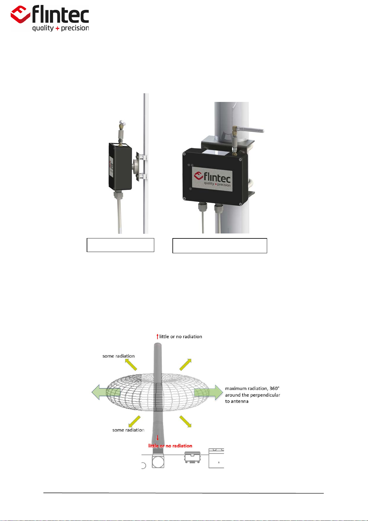
2.2. Antenna Recommendations ........................................................................................6
2.3.
Base Unit Connections
................................................................................................8
2.4.
Remote Unit (Wireless Load Cell)
.................................................................................9
2.4.1. Connect Load Cell to Remote Unit .......................................................................10
3.
Battery Installation
..........................................................................................................13
4. Equipment Maintenance..................................................................................................14
5. Operation .......................................................................................................................15
5.1.
Base Unit Channel Selection
......................................................................................16
6. Technical Specification.....................................................................................................18
7. Markings ........................................................................................................................20
7.1. Remote Unit (Transmitter) ........................................................................................20
7.2. Base Unit (Receiver) .................................................................................................20
Ordinary Location Markings...........................................................................................20
8. Product Dimensions.........................................................................................................21
8.1. Generic Load Cell......................................................................................................21
8.2. Remote Unit ............................................................................................................22
8.3. Base Unit.................................................................................................................23
9. Safety Information ..........................................................................................................24
9.1. Intended Usage........................................................................................................24
9.2. Lithium Batteries......................................................................................................24
9.3. Maintenance Safety .................................................................................................24
9.4. X-Mark Conditions....................................................................................................25
10. FCC Certification Statement..............................................................................................26
11. ISED RSS-Gen Notice........................................................................................................27
11.1. IC Certification Statement..........................................................................................27
12. RF Exposure Notice..........................................................................................................28
12.1. FCC & ISED Canada RF Exposure Notice ......................................................................28
12.2. Avis d'exposition FCC et ISDE Canada RF.....................................................................28
13. CCWR Control Drawing 0090977 .......................................................................................29

Doc No.0096489 Page 3of 29 V1.2 Issued 17 Aug 2020
1. Product Description
The CCWR is a wireless variant of our CC1 pump-off control load cell. The CCWR in conjunction
with an appropriate load cell can transmits polished rod load wirelessly, which solves the
industry wide problem of cable failures. After months of development in the field, working
hand-in-hand with end users, our design addresses the most demanding concerns raised.
The CCWR technology sets our product apart from all wireless products currently available in the
market. The primary advantage is extremely low power consumption. Despite the low power
consumption, the product can deliver a continuous flow of data, high signal strength and long
battery life. We also offer position sensing capability which is synchronized with the load
measurement. This eliminates the need for Hall effect sensors or inclinometers with costly
maintenance associated. The wireless enclosure also incorporates an independent
compartment for both the wireless technology and the battery. This allows for easy, single
handed access to the battery for replacement in the field. We carefully specified a pre-wired D-
cell battery is inexpensive and commercially available worldwide.
•Continuous Flow of Data: 100 Readings per Second.
•Low Power Consumption: 12-18 month Battery Life.
•High Signal Strength: > +12dBm, 30m-300m Transmission.
•HazLoc Approved: UL Rated Class 1, Division 1 environments (see label for full approval).
•On-Board Position: ±2% Accuracy
•Security: Proprietary Wireless Transmission Protocol
•Ease of Use: Independent Battery Access, Commercially Available Battery.
•Weatherproof: IP67 rating, Rated for use in -70°F to 175°F (-55°C to 80°C).
1.1.Accessories
•Base Unit (Receiver).
•Antenna.
•Extension Cable.
•Magnetic Cable Clamps (4x).
•Remote Unit (Transmitter).
•Lithium Battery.
•User Manual.
1.2. Optional Accessories
•P/N 52-0093380 – Pole Mount U Bolt Bracket.
•P/N 52-0089758 – DIN Rail Mounting Bracket.

Doc No.0096489 Page 4of 29 V1.2 Issued 17 Aug 2020
2. Mounting Instructions
IMPORTANT
The employees responsible for the equipment, installation and verification must take into
consideration all the actions concerning this subject specified in IEC 60079-14:2013 ed. 5.0
(Electrical installations design, selection and erection) standard. In addition to general
specifications associated with any system installed in hazardous locations, special attention
should be paid for specific requirements regarding intrinsic safety.
2.1.
Base Unit
The base of the device comes with a magnet to the rear for easy mounting to a metal surface
inside or outside of the pump controller cabinet. The base mounts outside the hazardous area
and is not intended to meet hazardous location safety standards. The antenna must be fitted
with the band-pass filter, as this forms part of the FCC/IC radio approvals.

Doc No.0096489 Page 5of 29 V1.2 Issued 17 Aug 2020
If the magnetic base is not directly attached, due to a non-metallic surface (or space
constraints), the base can be suitably fastened to any structure using brackets, plates or other
type of support.
_________________________________________________________________
IMPORTANT In order to achieve the best performance the antenna attached to the top
right corner of the base unit must be perpendicular/horizontal to the antenna polished rod as
shown in the above images.
_________________________________________________________________
You many optionally use an extension cable to mount the antenna. Make sure the RF filter is
connected directly to the base unit.
DIN rail mount
Pole mount with U-Bracket

Doc No.0096489 Page 6of 29 V1.2 Issued 17 Aug 2020
2.2. Antenna Recommendations
Omni Directional Antenna
CCWR base unit is equipped with an
omni-directional antenna to provide
the widest possible signal coverage.
RP-SMA Connector (Female)
The antenna is provided with a
threaded, weatherproof RP-SMA
female connector. This connector
must be properly tightened to the
male connector on the enclosure.
Vertical Alignment
Perpendicular/horizontal alignment
of the antenna, relative to the
polished rod is essential.
Line-of-sight
Is important to find, whenever
possible, a line of sight with the load
cell where minimal obstacles reside
along the RF path.
Note: Fresnel Zone, the area around
the visual line-of-sight that radio waves
spread out into after they leave the
antenna must be clear as possible.
Obstacles may weaken signal strength.
Antenna Height
The base unit antenna can be
positioned flexibly using the
antenna extension cable.
Mounting the antenna at a
higher position to the base
may help achieve better
propagation.
Note: The use of extension
cables that always represent
attenuation and signal
strength losses should be
avoided if possible.
Antenna Mating
The recommended torque
setting for the antenna/band-
pass filter is 5lbs (0.56Nm).

CCWR - User Manual
Doc No.0096489 Page 7of 29 V1.2 Issued 17 Aug 2020
Enclosure Mounting

CCWR - User Manual
Doc No.0096489 Page 8of 29 V1.2 Issued 17 Aug 2020
SIGNAL CABLE
COLOR CODE
RED Excitation + / Vref +
GREEN mV/V Signal + / mA +
WHITE mV/V Signal - / mA -
BLACK Excitation - / Vref -
YELLOW Shield (NC)
GRAY Optional analog
VIOLET Ground
POWER CABLE
COLOR CODE
BLACK Ground
YELLOW Shield
RED 12 to 24VDC
2.3.
Base Unit Connections
WARNING: Insulate unused leads to prevent shorting.

CCWR - User Manual
Doc No.0096489 Page 9of 29 V1.2 Issued 17 Aug 2020
2.4.
Remote Unit (Wireless Load Cell)
CCWR is mounted in the same way as other polished rod load cells.No special mounting
procedure is required.
________________________________________________________________
IMPORTANT
Position the remote unit (with the Flintec logo upright on the plastic enclosure).
________________________________________________________________

CCWR - User Manual
Doc No.0096489 Page 10 of 29 V1.2 Issued 17 Aug 2020
2.4.1. Connect Load Cell to Remote Unit
1. Loosen the 3 retaining screws.
2. Insert the load cell adaptor (3/4-14 NPT) and keep free/loose from the assembly.
Otros manuales para CCWR
1
Tabla de contenidos
Otros manuales de Electricidad industrial de Flintec
Manuales populares de Electricidad industrial de otras marcas

S&C
S&C Vista SD Manual de usuario

Murata
Murata GRM0335C2A7R3CA01 Series Manual de usuario

Siemens
Siemens 3VA9988-0BM10 Manual de usuario

Siemens
Siemens SITRANS LVS100 Manual de usuario

Murata
Murata GRM32ER60G227ME05 Series Manual de usuario

Siemens
Siemens SENTRON SUPERSWITCH 3KL82 Series Manual de usuario


