
Fire-Lite LED-10 series Manual de usuario
12 Clintonville Road, Northford, CT 06472 B
Document # 50400
10/27/97 Revision:
P/N 50400:B ECN 97-510
The LED-10 Series
RemoteFireAnnunciators
for use with the Fire
•
Lite
MS-5210UD
Fire Alarm Control/Communicator

2Document 50400 Rev B 10/27/97 P/N 50400:B

3
Document 50400 Rev B 10/27/97 P/N 50400:B
Contents
Section One: LED-10 Series Annunciators ...................................... 4
Features................................................................................................. 4
Figure 1-1: Component Summary......................................................... 5
Figure 1-2: Wiring to Terminals ............................................................. 6
SW1 DIP Switch Settings...................................................................... 7
Figure 1-3: SW1 DIP Switch Settings Example .................................... 7
Figure 1-4: SW2 DIP Switch Settings Example .................................... 8
Table 1-1: LED-10 Series Annunciator Addressing .............................. 9
Figure 1-5: Typical Configuration .......................................................... 9
LED Indicators and Piezo Sounder..................................................... 10
Switch Functions for LED-10 Only ...................................................... 11
Section Two: LED-10 Series Annunciators Mounting.................... 13
Figure 2-1: LED-10 Series Hardware.................................................. 13
Figure 2-2: LED-10 Series Backboxes................................................ 13
Figure 2-3: LED-10 Series Semi-flush Mounting ................................ 14
Figure 2-4: LED-10 Series Surface Mounting..................................... 15
Section Three: LED-10 Series Electrical Connections ................. 16
Figure 3-1: Power Connection............................................................. 16
Figure 3-2: LED-10IM Installation ....................................................... 17
Figure 3-3: EIA-485 Connection ......................................................... 18
Figure 3-4: Wiring FACP to LED-10 Series......................................... 19
Section Four: EIA-485 Shield Terminations ................................... 20
When the EIA-485 Shield is not in Conduit ........................................ 20
When the EIA-485 Shield is in Full Conduit ....................................... 21
Spare Slide-In Labels for LED-10 Series Annunciators................ 23
4Document 50400 Rev B 10/27/97 P/N 50400:B
Section One: LED-10 Series Annunciators
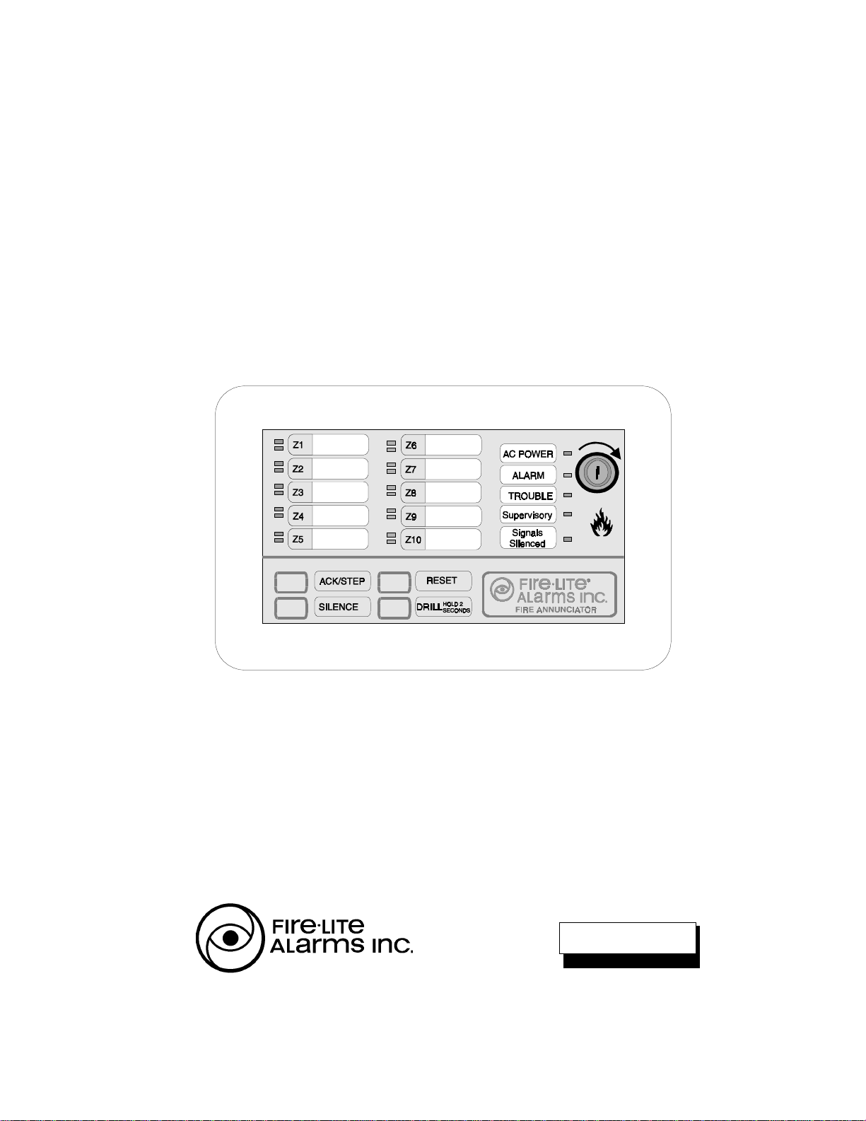
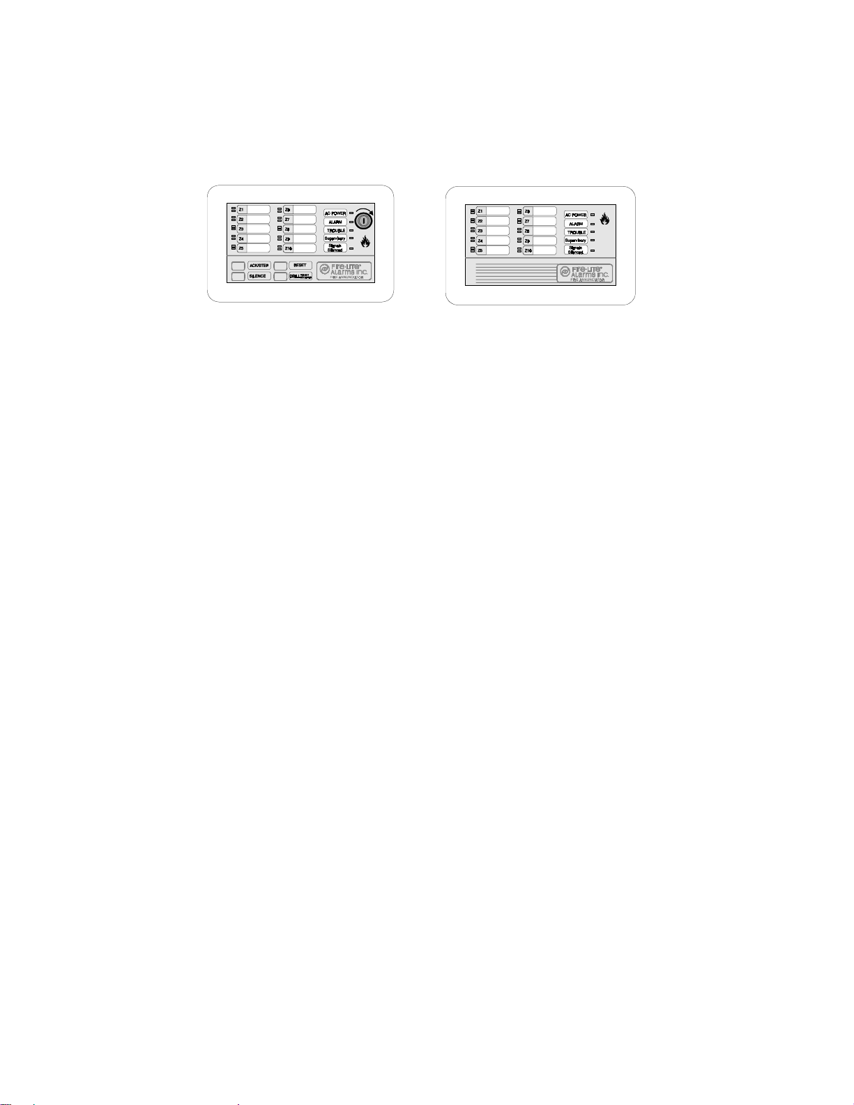
The Fire•Lite LED-10 Series Annunciators consist of the LED-10, LED-10L and LED-
10LS2. They are compact, attractive LED-type fire annunciators designed for use with
the MS-5210UD Fire Alarm Control Communicator. The LED-10L and LED-10LS2 are
models which do not have function switches or a key-switch. The LED-10LS2 is
intended primarily for Canadian installations since it provides zone 9 and 10 alarm LEDs
that are yellow for supervisory functions.
The LED-10 Series Annunciators are capable of displaying independent zone
fire alarm,
process monitor alarm, trouble and supervisory status. They also provide system
status LEDs to display Power, Alarm, Trouble, Supervisory and Signals Silenced
conditions. The LED-10 model is also capable of performing system acknowledge,
silence, drill and reset remotely.
Communication between the control panel and the LED-10 Series Annunciators is
accomplished over a two-wire serial interface employing the EIA-485 communication
standard. Up to 32 LED-10 Series Annunciators may be connected to the two-wire EIA-
485 circuit. The annunciators may be powered from the host FACP or remote, UL
listed, filtered, regulated power supplies.
Features - all models
• Zone Alarm and Trouble LEDs.
• System Status LEDs for Power (green), Alarm (red), Trouble (yellow), Supervisory
(yellow) and Signals Silenced (yellow).
• Local piezo sounder with alarm and trouble resound.
• Distinctly different flash rates for LEDs and piezo sounder distinguish system
status:
üfire alarm = 1 second on and 1 second off
üprocess monitor alarm = 1/4 second on and 1/4 second off
üsupervisory alarm = 1/2 second on and 1/2 second off
• EIA-485 connects to control panel terminal port (requires LED-10IM module).
• Plug-in terminal blocks for ease of installation and service.
• DIP switch controls transmit/receive mode.
• Up to 32 LED-10 Series Annunciators per MS-5210UD.
• Mounting options:
üSurface mount in three gang electrical box P/N: SBB-3
üSemi-flush mount in three-gang electrical box P/N: 10103 (2 3/16" min. depth)
üCan be located up to 6,000 feet (1,800 m) from the panel using 18 AWG wire
• Slide-in labels for custom labeling.
• Simple programming at MS-5210UD panel enables communications to LED-10
Series annunciators.
LED-10 LED-10L and LED-10LS2
5
Document 50400 Rev B 10/27/97 P/N 50400:B
LED-10 only:
• Function switches for:
üAcknowledge üSignal Silence üDrill üSystem Reset
• Enable/Disable key-switch for function switches.
• DIP switches control local functions such as piezo enable/disable, function
switches and key-switch enable/disable.
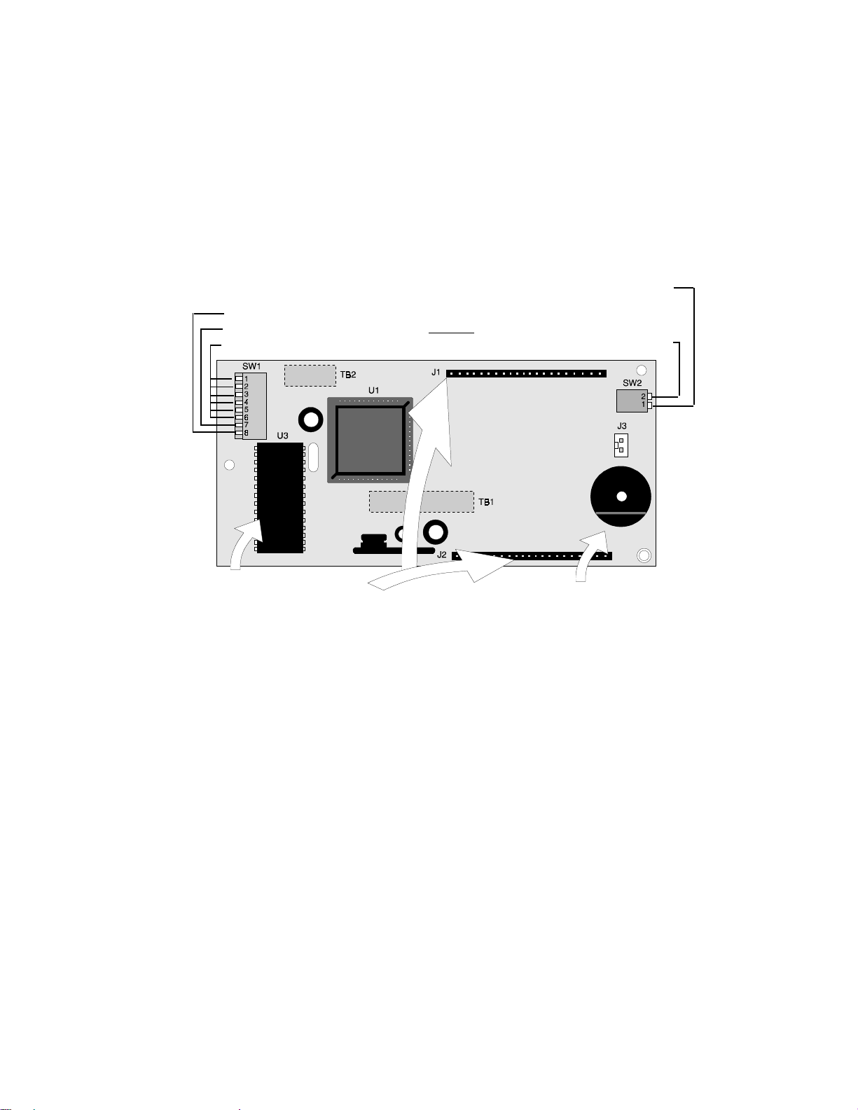
ROM PiezoSounder
TheLED-10 Seriessounder,ifenabled, willbeactivated
when any new alarm or trouble is received from the
panel. It is silenced by pressing an ACKNOWLEDGE or
SILENCE switch. Piezo must not be disabled without
approval of LAHJ (Local Authority Having Jurisdiction).
MembraneConnectors
Membrane switch connectors
Receive-Transmit/Receive only
not used
LED-10 Series Address
Key-switch Enable/Disable for LED-10 Only
(not used on the LED-10L or LED-10LS2)
Piezo Enable/Disable
Top view
Note: TB1 & TB2 are
located on backside of PCB
Figure 1-1: Component Summary
6Document 50400 Rev B 10/27/97 P/N 50400:B
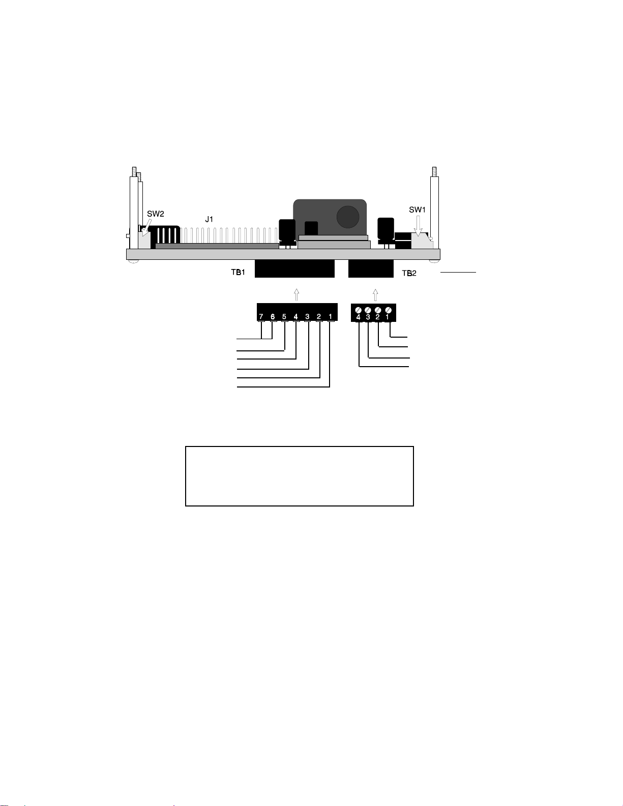
Figure 1-2: Wiring to Terminals
Current Consumption @ 24 VDC nominal (filtered)
Normal/Standby (no activity): 23 mA
Trouble Condition: 31 mA
Alarm: 28 mA (1 zone in alarm)
40 mA (all 10 zones in alarm)
AC Fail: 24 mA
Note: These connections must be power-limited and the +24 volt nominal power (18 VDC to 26 VDC)
must be filtered.
Earth Ground Option
-24 VDC OUT
-24 VDC IN
+24 VDC OUT
+24 VDC IN
No connection
+EIA-485
-EIA-485
Shield
No connection
Side view
(rotated 180
o
from above
[Top] view)
7
Document 50400 Rev B 10/27/97 P/N 50400:B
SW1 DIP Switch Settings
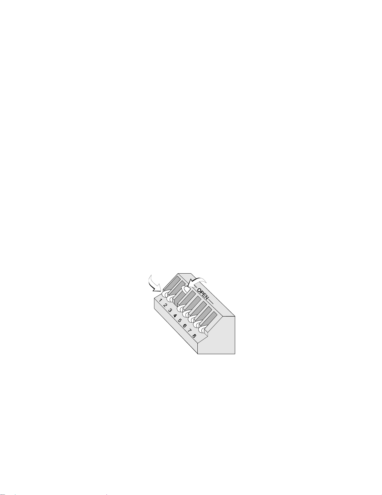
The OPEN position on SW1 is the OFF state. Refer to Figure 1-3 for an explanation of
DIP switch positions. SW1 switch settings are as follows:
1 through 6 - LED-10 Series annunciator address switches.
The first six switches are used to set the address of the annunciator. The OFF
(OPEN) up position equals a binary 1 and the ON down position equals a
binary 0. Refer to Table 1-1 for information on setting these switches for
specific addresses. Each LED-10 Series annunciator connected to the EIA-
485 communication bus must have a unique address.
7 - Not used
8 - ON = Receive/Transmit, OFF (OPEN) = Receive Only
Switch 8 set to ON position enables Receive/Transmit mode for the LED-10
Series annunciator. This allows the annunciator to receive and display system
status information and to transmit supervision status. It also allows the LED-10
model to transmit system control data such as Acknowledge/Step, Reset,
Signal Silence and Drill. Switch 8 set to the OFF position enables Receive
Only mode which allows the annunciator to receive and display system status
information but prevents supervision status from being transmitted back to the
FACP. It also prevents function switch operation on the LED-10 model. To
ensure annunciator supervision for all LED-10 Series annunciators and
function switch capability for the LED-10 model, each annunciator connected to
the EIA-485 communication bus must have a unique address and should be
set to enable Receive/Transmit Mode.
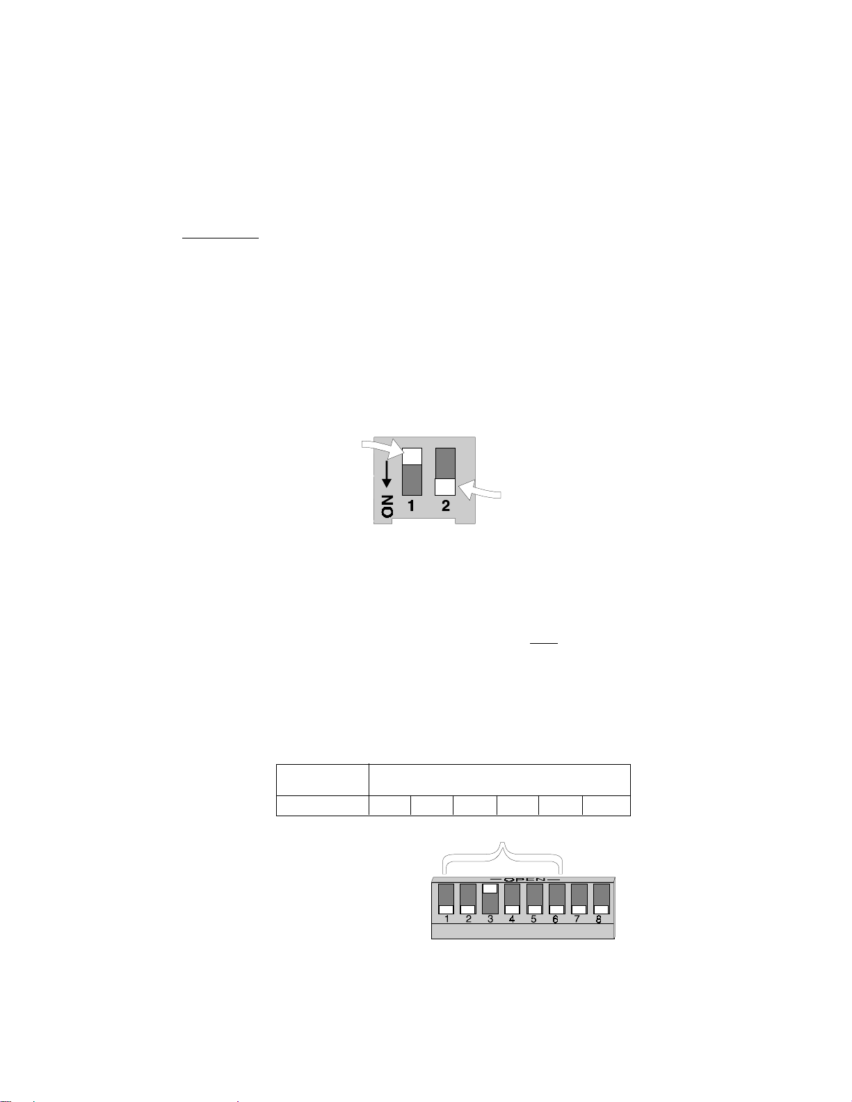
Figure 1-3: SW1 DIP Switch Settings Example
NOTE - SW1 DIP switch settings as illustrated in Figure 1-3 are as follows:
1) DIP switches 1 - 6: Address 08 (see Table 1-1).
2) DIP switch 7: Not used.
3) DIP switch 8: ON = Receive/Transmit
DOWN POSITION = ON UP (OPEN) POSITION = OFF
8Document 50400 Rev B 10/27/97 P/N 50400:B
SW2 DIP Switch Settings
SW2 switch settings are as follows:
1 - LED-10 Only (not used on LED-10L and LED-10LS2)
ON = Key-switch Enable, OFF = Key-switch Disable.
Switch 1 set to the ON position enables the key-switch operation. The key-
switch may now be used to enable LED-10 model membrane (control) switches,
allowing remote switch functions, or lockout the switches, preventing remote
switch functions. Switch 1 set to the OFF position disables the key-switch
operation. Refer to Operation Section for key-switch function description.
2 - ON = Piezo sounder enabled, OFF = Piezo sounder disabled.
CAUTION: Piezo sounder must not be disabled without prior approval of the
Local Authority Having Jurisdiction.
UP POSITION = OFF
DOWN POSITION = ON
LED-10 Series Addressing
SW1 DIP switches 1 through 6 are used for addressing the LED-10 Series annuncia-
tors.
Each device connected to the EIA-485 communication bus must have a unique
address.
This allows specific data to be transmitted between the FACP and that device
and for individual supervision of each annunciator by the FACP. Switch settings and
the corresponding addresses are shown in Table 1-1. (Address '00' is invalid).
Note: 1 = Switch in the UP (OPEN) position.
0 = Switch in the DOWN position.
Example: ADDRESS SWITCH SETTINGS
1 2 3 4 5 6
08 0 0 1 0 0 0
Addressing Switches
Figure 1-4: SW2 DIP Switch Settings Example

9
Document 50400 Rev B 10/27/97 P/N 50400:B
ADDRESS SWITCH SETTINGS ADDRESS SWITCH SETTINGS
1 2 3 4 5 6 1 2 3 4 5 6
INVALID 0 0 0 0 0 0 17 0 1 0 0 0 1
01 0 0 0 0 0 1 18 0 1 0 0 1 0
02 0 0 0 0 1 0 19 0 1 0 0 1 1
03 0 0 0 0 1 1 20 0 1 0 1 0 0
04 0 0 0 1 0 0 21 0 1 0 1 0 1
05 0 0 0 1 0 1 22 0 1 0 1 1 0
06 0 0 0 1 1 0 23 0 1 0 1 1 1
07 0 0 0 1 1 1 24 0 1 1 0 0 0
08 0 0 1 0 0 0 25 0 1 1 0 0 1
09 0 0 1 0 0 1 26 0 1 1 0 1 0
10 0 0 1 0 1 0 27 0 1 1 0 1 1
11 0 0 1 0 1 1 28 0 1 1 1 0 0
12 0 0 1 1 0 0 29 0 1 1 1 0 1
13 0 0 1 1 0 1 30 0 1 1 1 1 0
14 0 0 1 1 1 0 31 0 1 1 1 1 1
15 0 0 1 1 1 1 32 1 0 0 0 0 0
16 0 1 0 0 0 0
NOTES:
1) EIA-485: Maximum of 6,000 feet (1,800 m) total cable length from FACP to LED-10 Series
annunciators. Circuit is power-limited.
2) Up to 32 LED-10 Series annunciators may be used on the EIA-485 circuit. The MS-5210UD
can power a maximum of seven annunciators. If additional annunciators are connected, the
Fire•Lite FCPS-24F may be used to supply additional power. (Power supplies used for this
purpose must have their negative terminals commoned together).
3) Between each annunciator are four wires: A twisted-shielded pair for data communications and
a pair for 24 VDC power.
4) A mix of LED-10 Series annunciators can be connected to the same EIA-485 circuit.
Figure 1-5: Typical Configuration
Table 1-1: LED-10 Series Annunciator Addressing
TypicalConfiguration
The LED-10 Series annunciators indicate the status of the MS-5210UD, display zone
status and require no programming. In addition, the LED-10 model offers multiple
annunciator locations with the capability of remote Acknowledge, Signal Silence, Drill
and Reset functions.
10 Document 50400 Rev B 10/27/97 P/N 50400:B
LED Indicators and Piezo Sounder
The LED-10 Series annunciators provide LEDs which indicate the system and zone
status of its associated MS-5210UD fire alarm control panel.
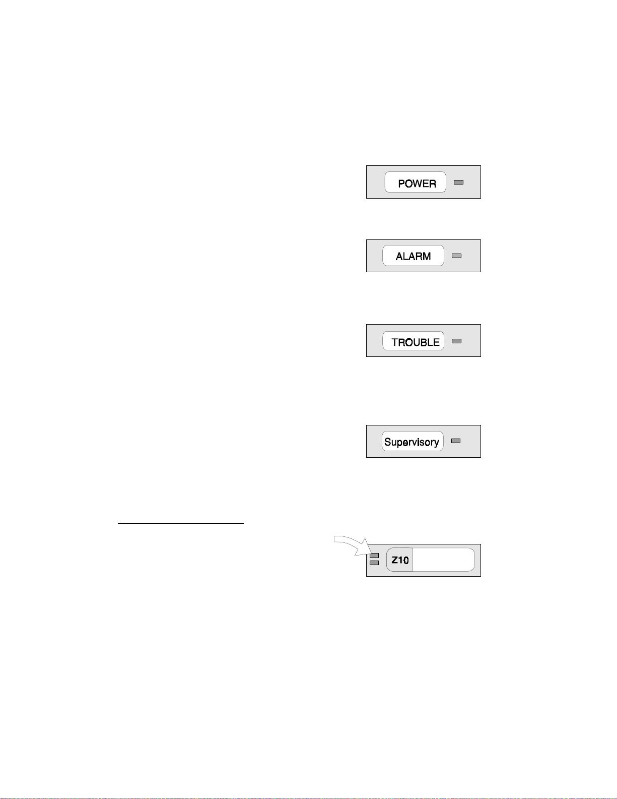
AC Power
This is a green LED which illuminates if AC power is
applied to the host FACP. The green LED will turn
off if AC power to the host FACP is lost.
Alarm
This is a red LED that flashes (1 second on, 1
second off) when one or more fire alarms occur. The
piezo sounder turns on steady for alarm. The LED
illuminates steadily and the piezo silences when an
Acknowledge or Silence switch is pressed. The
Alarm LED turns off when the Reset switch is
pressed after the alarm condition has been cleared.
Trouble
This is a yellow LED that flashes (1 second on, 1
second off) when one or more trouble conditions
occur. The piezo sounder pulses (1 second on, 1
second off). The LED turns on steady and the piezo
silences when an Acknowledge or Silence switch is
pressed. The LED turns off when all trouble conditions are cleared. This LED will
also illuminate if the microprocessor watchdog circuit within the annunciator is
activated.
Supervisory
This is a yellow LED that flashes (½ second on, ½
second off) when one or more supervisory conditions
occur, such as a sprinkler valve tamper condition.
The piezo sounder pulses (½ second on, ½ second
off). The LED illuminates steadily and the piezo silences when an Acknowledge or
Silence switch is pressed. The Supervisory LED turns off when a Reset switch is
pressed after clearing the supervisory condition.
LED-10 and LED-10L Only
Zone Alarm - Zones 1 through 10
This is a red LED that flashes when a fire alarm,
supervisory alarm or process monitoring alarm
occurs on the corresponding zone. The LED flashes
at a 1 second on/1 second off rate for a fire alarm
condition, a ½ second on/½ second off rate for a supervisory alarm and a ¼ second
on/¼ second off rate for a process monitoring alarm. The piezo sounder will pulse
at a rate corresponding to the flashing LED. The LED illuminates steadily and the
piezo silences when an Acknowledge or Silence switch is pressed. The LED turns
off when the fire alarm, process monitoring alarm or supervisory alarm is cleared on
the corresponding zone and the Reset switch is pressed.
Note: Be certain to use customized slide-in label to identify the zone function, since
the red LED will flash for a variety of conditions as programmed in the FACP. Refer
to the MS-5210UD Manual P/N 50193 for details.
Este manual sirve para los siguientes modelos
2
Tabla de contenidos
Otros manuales de Alarma de incendios de Fire-Lite

Fire-Lite
Fire-Lite C304(A Manual de usuario

Fire-Lite
Fire-Lite ECC-50 Manual de usuario

Fire-Lite
Fire-Lite CMP-2401B Manual de usuario

Fire-Lite
Fire-Lite 411 Manual de usuario

Fire-Lite
Fire-Lite 300 Series Manual de usuario

Fire-Lite
Fire-Lite LCD-80F Manual de usuario

Fire-Lite
Fire-Lite LDM-32F Manual de usuario

Fire-Lite
Fire-Lite BG-12SL Manual de usuario

Fire-Lite
Fire-Lite BG-12LX Manual de usuario

Fire-Lite
Fire-Lite MS-9200(C/E) Manual de usuario


