FibroPool FH-020 Hoja de especificaciones

Swimming Pool Heat Pump
—Operation and Installation Manual—
MODEL
FH-020

CONTENTS
INTRODUCTION
Index...........…………………………………......................................……………………………......…………... 2
The unit ………………………………………………………………………………………………………….................. 2
S FETY INSTRUCTIONS …………………………………………………………………………………………... 4
Electrical Installation Warning ….………………………………………………………………………………………….… 4
Location Warning……………………………………………………………………………………………………………… 5
CONTENTS OF THE BOX …………………………………………………………………………………………….…… 6
OVERVIEW OF THE UNIT ……………………………………………………………………………………….……… 7
EXPLODED VIEW…………………………………………………………………………………………….…………………. 8
INST LL TION …………………………………………………………………………………………….…..….…….… 9,10
Installation AREA …………………………………………………………………………………………….…..….....…. 9
Optimize our installation .………………………………………………………………………….…………………… 9
Water connection …………………………………………………………………………………..…………….………….. 9
Electrical connection ……………………..……………………………………………………………………….….……… 9
Trial running …………………………………………………………………………………………….……..……………….. 10
OPER TING THE UNIT …………………………………………………………………………………………….……… 11
Features and functions …………………………………………………………………………………………….……….. 11
User interface ……………………………………..…………………………………………………………………………… 11
Buttons …………………………………………………………………………………………….……………………….… 12
S stem fault table…………………………………………………………………………………………………………… 13
P R METER CODES, ERROR CODES …….....……………………………….……………….……………. 13
Parameter list ….........………………………………………………………………………….……………………. 14
M INTEN NCE …………………………………………………………………….……………………………………….. 15
TROUBLESHOOTING …………………………………………………………….………………………………………… 16
ENVIRONMENT L INFORM TION ……………………………………….………………………………………… 17
WIRING DI GR M …………………………………………………………….…........……………………………. 18
W RR NTY INFORM TION…………………………………………….……………………………………………. 19
READ THIS MANUAL CAREFULLY BEFORE STARTING UP THE UNIT. DO NOT THROW IT AWAY.
KEEP IT IN YOUR FILES FOR FUTURE REFERENCE.
BEFORE OPERATING THE UNIT, MAKE SURE THE INSTALLATION HAS BEEN CARRIED OUT BY A LICENSED
AND COMPETENT PROFESSIONAL . IF YOU FEEL UNSURE ABOUT INSTALLATION OR OPERATION,
CONTACT YOUR DEALER FOR ADVICE AND INFORMATION.
2

INTRODUCTION
This manual includes all necessary information about the unit. Please read this manual carefully
before you use and maintain pump.
The unit
The swimming pool heat pump is one of the most economical s stems to heat swimming pools
efficientl . Using the free, renewable energ from the air, it delivers up to 6.2 times more energy in
heating than a traditional heating s stem such as a gas boiler or electric heater, saving 85% on energ
costs. The swimming pool heat pump provides comfortable swimming temperatures ear round in
milder climates and extended swimming seasons in the cooler/ drier climates
Ecological and economical heating
B making use of the renewable energ in the outside air, it consumes much less energ with low
carbon emissions. Utilizes environmentall and ozone-friendl technolog , R410A.
Titanium heat exchanger
Advanced titanium heat exchanger guarantees a long life span and protects against the damaging
effects of corrosion or rust. B using a titanium heat exchanger, the heat pump is compatible with
all t pes of water treatment such as chlorine, bromine and salt.
Multiple functions
- Cooling and heating functions
- Auto-operation, Auto-restart, Auto defrost
- Timer on/off: no attendance is required
- Wide ambient working condition: -5°C to 43°C (23°F to 109°F)
Reliable operation
To guarantee the stable operation and safet of the unit, multiple protection devices have been
built into the design, including insufficient water flow protection, high/low pressure protection,
overload protection and compressor protection.
Safe use
The unit runs without oil, gas or an other hazardous substance, removing the risk of intoxication,
smell, combustion, pollution from leakage.
Self-diagnosis
In case of a malfunction, the pump will make a self-diagnosis b displa ing an error code on the
control panel, no guesswork necessar .
3

S FETY INSTRUCTIONS
To prevent injur to the user, others, or propert damage, the following instructions must be carefull
followed. Ignoring these instructions ma result in injur or death.
Install the unit onl if it complies with local codes, b -laws and standards. Check the main voltage and
frequenc . This unit is onl suitable for grounded circuits, connection voltage 220 – 240 V ~ / 60Hz. It
cannot be converted to 120 volts.
The following safet precautions should alwa s be taken into account:
-Be sure to read the following WARNING before installing the unit.
-Be sure to observe the cautions specified here as the include important items related to safet .
-After reading these instructions, be sure to keep them in a hand place for future reference.
Installation must be done by a licensed and competent professional
Incorrect installation could cause injur or death due to fire, electric shock, the unit falling or leakage of
water. BE SURE ALL LOCAL CODES ARE FOLLOWED.
Use the specified electrical wires and attach wires firmly to the terminal board (connection in such a
way that the stress of the wires is not applied to the sections).
THIS UNIT REQUIRES 220-240 VOLTS, C, 60 Hz, 20 mp DU L BRE KER WITH APPROPRIATE SIZE WIRE.
The weather-proof wire provided with the unit is 8 feet long. Some municipalities DO NOT authorize
usage of weather-proof wires, and require conduit protection.
This unit runs on 220 - 240 volts only. It cannot be used with 120 volts electricity
Be sure to use the provided or specified parts for the installation work.
Be sure to use the 'EQUIPOTENTI L BONDING CONNECTION “ on the chassis of the heater. Please
connect this bond to a minimum of #8 copper wire; along with the rest of the metal parts around the
pool, in accordance with NEC 2005 -680.26 Electrical code.
The unit must always have a GROUNDED connection, as well as a bonding connection
Do not use an extension cord to connect the unit to an electrical power supply.
Do not move/repair the unit yourself.
Before proceeding with an maintenance, service or repair work, electrical lines must be
DISCONNECTED. Onl a licensed/competent technician should work on this unit.
Use only Genuine FIBROPOOL® P RTS for replacement. ll parts can be obtained from Fibropool,
www.fibropool.com
4

Do not install the unit in a place where there is a fire hazard:
G S LE KS. If there is a gas leak and gas accumulates in the area surrounding the unit, it could cause
an explosion.
UNDER THE ROOF E VES . Although the unit is weatherproof, a direct pour of water from the roof is
likel to penetrate the shell and cause a shortage. Please install the heater in an open area exposed to
weather, but not beneath the roof line
ON WET SURF CE. Wet areas will cause metal corrosion and shorten the life of our heater
LOWER TH N SURROUNDING RE S. Install our heat pump on an equipment pad or concrete blocks
to prevent accumulated water from entering the unit from bottom.
IN ENCLOSED RE S. The heat pump needs fresh air to operate. Do not install in equipment rooms or
enclosed areas. If this is a must, be sure to install an air fan to suppl fresh air to the room, at a rate of
NO LESS THAN 3,000 cfm.
Do not open the unit when the power is ‘ON’.
Alwa s shut ‘OFF’ the power b disconnecting the suppl breaker or service disconnect when cleaning
or servicing the unit. Electrical shock, Injur or death can occur, as the unit works on HIGH voltage
Do not continue to run the unit when there is something wrong or there is a strange smell.
The service disconnect must be pulled off or breaker turned off in case of an suspicious condition.
Do not put your fingers or other items into the fan.
The ventilator runs at high speeds, potentiall causing serious injur .
Do not block the drain holes on the bottom.
The unit will SWE T heavil during operation. This is commonl mistaken for a leakage, but is
actuall CONDENSATION, moisture in the air draining.
Provided elbow can snap to the bottom of the heater and ma be directed b attaching a hose.
5

CONTENTS OF THE PRODUCT BOX
Before starting the installation, please make sure that all parts are found inside the box.
The Unit Box
Item Image
*Swimming pool heat pump
**Operation and Installation
Manual
***Union set
****Drain adapter elbow
( inside the service panel)
6

OVERVIEW OF UNIT
Unit Dimensions Required Clearance
- Height 1'-10” 12”- top
B - Length 3'-0” 36” on service panel side, 12” on the far side
C - Width 1'-3” 12 “ on both sides
7

EXPLODED VIEW
1Cover 10 Chassis 19 Controller
2Fixed frame 11 Fan motor 20 Controller mounting board
3Front panel 12 Compressor 21 Four wa valve
4Wire controller 13 Evaporator 22 Titanium heat exchanger
5Copper tube 14 PCB 23 EEV
6Motor bracket 15 Support column 24 Low pressure switch
7Left side panel 16 Rear side panel 25 High pressure switch
8Guide air circle 17 Pressure gauge 26 Copper tube
9Fan blade 18 Cable fixing head 27 Maintenance panel
8
INST LL TION
Installation area
Install the unit on a flat, horizontal and stable surface. An HVAC equipment pad is ideal, although 4“ thick
concrete blocks will work as well.
To optimize installation
Allow a minimum of 12” of clearance on all 3 sides, but ensure 36” in front of the service panel
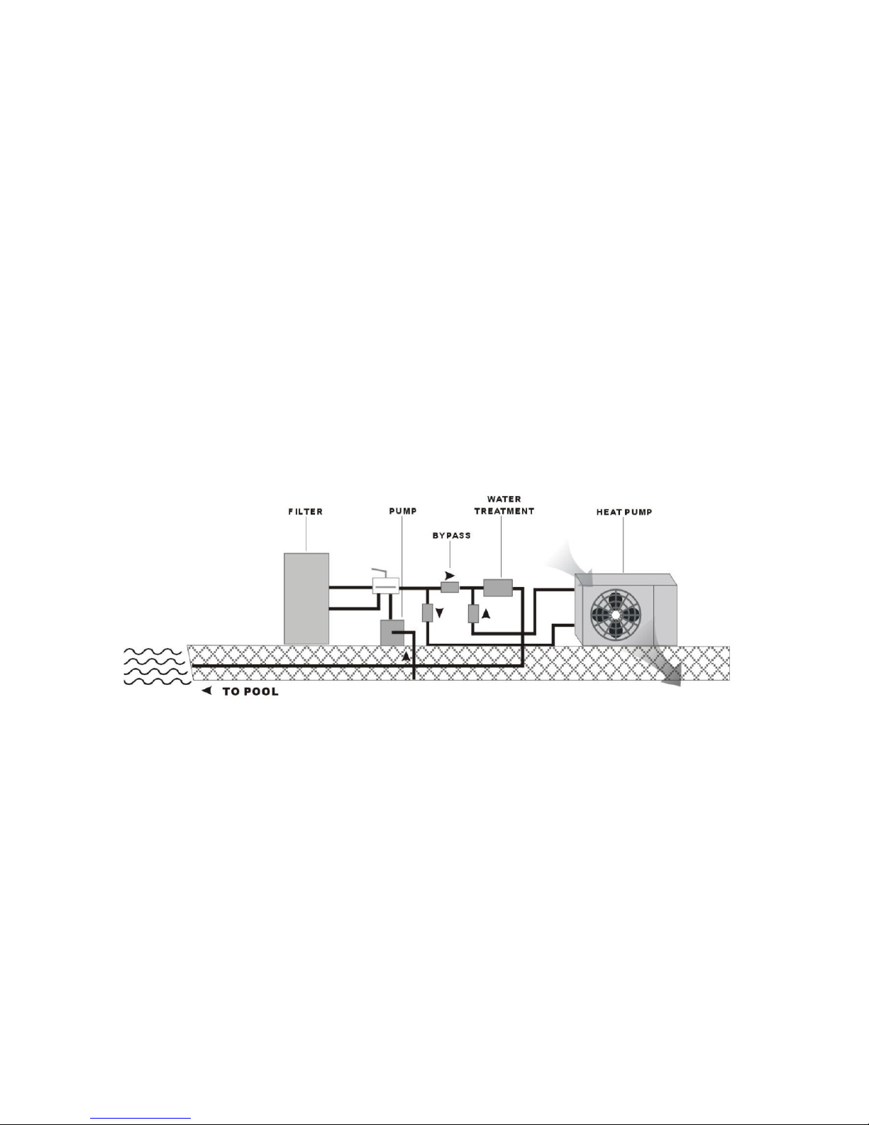
Water connection
The heat pump can be connected to the filtration circuit b one of two methods:
1. With a 3-valve
b pass, placed after the pump and filter. This allows the user to regulate water flow to the pump and
isolate the unit completel for maintenance.
2. Inline with the
s stem. This will somewhat reduce the flow rate of the filtration s stem on large circulation pumps.
NOTE
If our pool has a water treatment s stem (chlorinator, salt generator, brominator etc...) installed, the b pass
must be installed before the water treatment. A check valve after the heater, before the treatment s stem is
recommended but not required.
Electrical connection
Electrical suppl must be installed b a licensed electrician. This unit uses a double pole, 230-240 Vac, 60 Hz
circuit, with a 20-amp breaker. The unit will use a maximum of 9 amps of electricit during operation.
9

Trial running
After connecting water to the pool s stem perform a test run.
Ensure that:
Appliance is horizontal and on a firm base.
Plumbing is firml connected, using the approved t pe of pvc primer, glue or couplings.
Electrical wire is firml connected (all screws tightened correctl at terminals and intermediate
circuit breaker), insulated and GROUNDED correctl .
TURN ON YOUR POOL CIRCULATING PUMP “ON”
TURN ON THE BREAKER FOR THE HEATER
TURN ON YOUR HEATER WITH THE “ON/ OFF” SWITCH
OBSERVE THAT THE HEATER STARTS WITHIN 1 MINUTE BY KEEPING AN EYE ON THE PRESSURE
GAUGE.
ONCE THE HEATER TURNS ON, PRESSURE WILL CLIMB. LEAVE IT RUNNING FOR 5 MINUTES TO ASSURE THAT
ALL PARAMETERS ARE CORRECT
◦
ATTENTION: THE HEAT PUMP ONLY FUNCTIONS WHEN WATER FLOW IS PRESENT.
10
Tabla de contenidos
Otros manuales de Bomba de calor de FibroPool


Manuales populares de Bomba de calor de otras marcas


Mitsubishi Electric
Mitsubishi Electric PUZ-SWM60VAA Manual de usuario

Dimplex
Dimplex LI 16I-TUR Guía del usuario

Carrier
Carrier WSHP Open v3 Guía de configuración rápida

TGM
TGM CTV14CN018A Manual de usuario

Carrier
Carrier 38MGQ Series Manual de usuario

Kokido
Kokido K2O K880BX/EU Guía de solución de problemas

Viessmann
Viessmann VITOCAL 300-G PRO Type BW 2150 Guía rápida

Carrier
Carrier 48EZN Manual de usuario

Viessmann
Viessmann KWT Vitocal 350-G Pro Series Instrucciones de funcionamiento

Ariston
Ariston NIMBUS Manual de usuario

Weishaupt
Weishaupt WWP L 7 Guía del usuario

GE
GE Zoneline AZ85H09EAC Manual de usuario