
Fermont MEP-831A Manual de usuario

1
UNITED STATES MARINE CORPS
MARINE CORPS ENGINEER SCHOOL
UTILITIES INSTRUCTION COMPANY
PSC 20069
CAMP LEJEUNE, NORTH CAROLINA 28542-0069
MEP-831 GENERATOR CHARACTERISTICS, CAPABILITIES,
COMPONENTS, OPERATIONS AND PMCS CLASS
1. MEP-831A CHARACTERISTICS AND CAPABILITIES.
a. The MEP 831A is a 3kW (3000 watt) generator producing
60Hz of electric power. The MEP 831A is skid mounted with fork
lift provisions.
b. The MEP 831A weighs 304lbs dry, and 334lbs with a full
fuel tank. The MEP 831A is 34.8” long, 27.8” wide, and 26.5”
tall. The MEP 831A has six lifting handles and four tie down
rings. The MEP 831A can be manually lifted, or moved by
forklift.
c. The MEP 831 has a hinged enclosure that allows quick
access for preventive and scheduled maintenance. The cooling
system for the MEP 831A is a thermostatically cooled by two
fans.
d. The MEP 831A has a single-cylinder, air cooled, direct
injection, four stroke Yanmar diesel engine. The engine operates
between 3000 to 3600 RPM (6.7 HP at operating speed). The
maximum RPM rating is 3800 RPM. The diesel engine for a MEP 831A
has an oil capacity of 1.2 quarts (1.1 liters), and is consumed
at 0.04 ounce (1.18 ml) per hour at a rated load.
e. The MEP 831A is equipped with a four gallon fuel tank,
allowing eight hours of continuous operation at a full load. The
MEP 831A is designed to consume .5 gallons per hour at a rated
load. When the MEP 831A is connected to an auxiliary fuel
system, it will be continually replenished. The MEP 831A is
designed to use either diesel fuel type 1 (DF1) or 2 (DF2), and
turbine fuel JP-8.
f. The MEP 831A has 24VDC cranking system. The MEP 831A has
a Permanent Magnet Alternator (PMA) with a frequency converter.

2
g. The output voltages are a 2-plug 120VAC convenience
receptacle with Ground Fault Circuit Interrupter (GFCI), single
phase, 2 wire, 120VAC, or single phase, 3 wire, 120/240VAC. The
current output for the MEP 831A is 31 amps max for 120VAC, and
16 amps max for 120/240VAC.
PHYSICAL DESCRIPTION
Generator Set:
Manufacturer
Fermont
Model
MEP-831A
Fuel Tank Capacity (gal)
4
Fuel Type
Diesel/JP-8
Engine
Manufacturer
Yanmar
Model
L70AE-D/DE
Type
4 cycle, air cooled
Number of Cylinders
1
Speed (RPM)
3000 to 3600
Dimensions
Length (in)
35
Width (in)
28
Height (in)
27
Weight
Dry (lbs)
304
Wet (lbs)
334
Power Requirements
A/C Generator
Manufacturer
Dewey Electronics
Type
Rotating field, synchronous
Phase
1
Current Ratings (amps)
60Hz
120 volts, 2 wire
31a
120/240 volts 3 wire
16a
2. COMPONENTS OF THE TACTICAL QUIET GENERATOR (TQG).
a. Major Components.
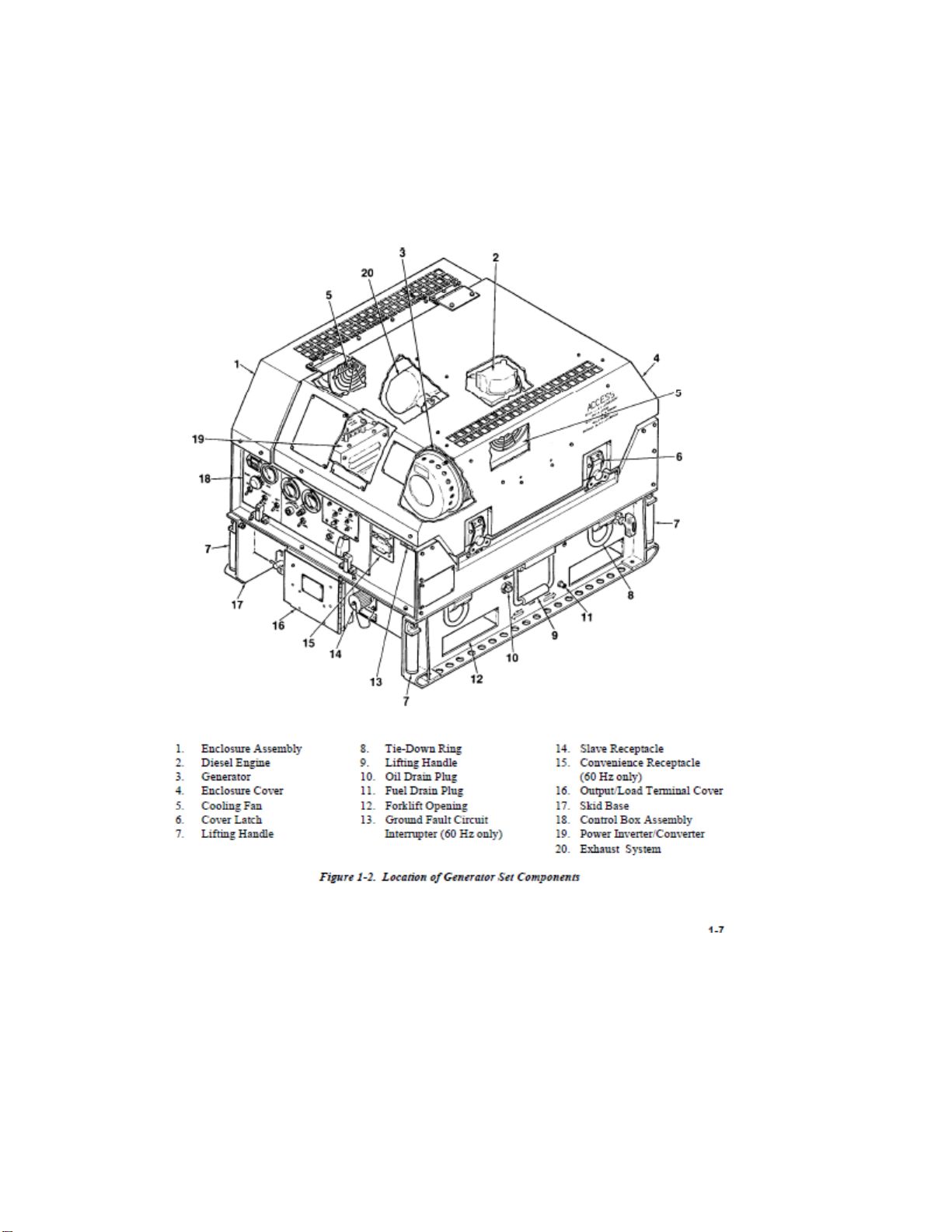
(1) Enclosure Assembly. The enclosure assembly (1,
Figure 1-2), supports the control box assembly, cooling air
system, and exhaust assembly components. It protects the
engine, generator, and other internal components from damage.
It incorporates a fire retardant acoustical insulation to reduce
noise levels, and acts as a shield to reduce electromagnetic
pulse effects on generator set components.

3
(2) Enclosure Cooling and Ventilation System. Air
intake openings and engine intake ducts at the rear of the
enclosure assembly allow for the engine cooling using external
air. Two thermostatically controlled fans (5, Figure 1-2)
mounted in the enclosure assembly activate during high
temperature conditions to drive hot exhaust air through openings
in the enclosure.
(3) Skid Base. The welded skid base (17, Figure 1-2)
provides the main structural support for the generator set. The
engine/generator assembly is mounted to the skid base with
vibration isolators which isolate engine generated vibration
from the rest of the generator set. The generator set’s plastic
fuel tank is contained within the skid base, as is the 24VDC
battery.
(a) The skid base contains four swing-out lift
handles (7), two standard lifting handles (9), four tie-down
rings (8), and two forklift openings (12).
(b) An oil drain plug (10) and fuel drain plug (11)
protrude through openings on the skid base, on the right side of
the generator set.
(c) A 24VDC slave receptacle (14) and load terminal
connections (behind cover (16)) are mounted to the skid base at
the rear of the generator set.
(4) Battery. A 24VDC battery, mounted in the skid base,
provides cranking power for the engine as well as DC power for
the control system. The battery’s location in the skid base
permits easy servicing. Openings in the enclosure assembly vent
escaping battery gases to the atmosphere, preventing gas build-
up inside the enclosure.
(5) Exhaust System. The generator set exhaust system
(20) consists of a muffler and exhaust piping. Engine exhaust
exits the generator set through an opening in the top of the
enclosure assembly. Insulating material on the exhaust system
components protects maintenance personnel against potential burn
hazards and reduces heat rejection into the enclosure assembly.
WARNING
Engine exhaust gas (Carbon Monoxide) is a deadly odorless,
colorless, poisonous gas. Avoid breathing it.

4
(6) Control Box Assembly. The control box assembly is
mounted to the enclosure assembly at the rear of the generator
set. Instruments, controls, and indicators required to operate
the generator set are located on the control box assembly. The
control box assembly consists of a control panel (18, Figure 1-
2), ground fault circuit interrupter, (13) (60Hz only).
(a) The control panel (18) portion of the box is
hinged to allow access for testing and maintenance.
(b) The Control Panel Contains the Following
Instruments and Switches:
1. HOURS Meter
2. FUEL LEVEL Gauge
3. VOLTAGE Meter
4. LOAD Meter
5. START/RUN/STOP Switch
6. EMERGENCY STOP Switch
7. AUX FUEL Switch
8. PREHEAT Switch
9. VOLTAGE ADJUST Switch
10. BATTLE SHORT Switch
11. Fault Indicator Module
a. The Fault Indicator Module Contains
Lights that Indicate the Following Generator Set Conditions:
(1) ENGINE HIGH TEMP
(2) LOW OIL PRESSURE
(3) NO FUEL
(4) OVERVOLTAGE
(5) OVERLOAD SHORT CIRCUIT

5
(6) BATTLE SHORT ON.
(7) Output Terminals and Slave Receptacle. The output
terminal board and ground terminal are located on the generator
set skid base, just below the control box assembly. A hinged
cover (16, Figure 1-2) allows access to the three load terminal
and single ground terminal. An insulated wrench, used for
connecting wires to terminals, is secured to the rear of the
hinged cover. A filter mounted to the back of the load
terminals prevents Electro-Magnetic Interference (EMI). The
generator’s 24VDC slave receptacle is mounted to the skid base,
to the right of the output terminals.
(8) Engine/Generator Assembly. The engine/generator
assembly (Figure 1-3) consists of a single-cylinder engine (14),
permanent magnet generator (5), and associated electrical, fuel
and oil components, The engine/generator assembly is mounted to
the skid base (8) with vibration mounts (7) to prevent engine
vibration from affecting the operation of the generator set
components. A fuel drain plug (9) and oil drain plug (10) allow
maintenance to drain engine fluids.
WARNING
Exposed fuel and fuel vapor can ignite or explode, resulting
in possible serious injury or death.
WARNING
Electrocution Hazard
Electrical high voltage cannot be seen but it can kill you,
render you unconscious, or severely burn you. Failure to
observe safety precautions may result in serious injury or
death.

6
(9) Engine. The generator set is equipped with a single
cylinder; air cooled, direct injection, four stroke cycle,
diesel engine (14, Figure 1-3). The engine is designed to
operate between 3000 and 3600 RPM. The engine has self-contained
oil lubrication and fuel systems. The engine is equipped with
an air filter (2), muffler (3), 24VDC starter motor (4),
manifold heater (15), engine high coolant temperature switch
(12), engine oil low pressure switch (12), and oil fill cap and
gauge (11). A rope pulled recoil system (1) permits manual
start of the engine without the battery. Engine cooling is
provided by a flywheel fan, which forces air over the cylinder
fins and engine components. The fan is completely guarded to
prevent inadvertent contact during operation.
(10) Generator. The permanent magnetic generator (5,
Figure 1-3) consist of four three phase isolated AC output
windings. Voltage output is proportional to engine speed
(approximately 190VAC at 3kW, 3450 RPM). The rotating portion
of the generator is mounted directly to the engine, on the
engine crankshaft extension, without a bearing.
(11) Power Inverter/Converter. The power inverter/
converter (19, Figure 1-2) is located in the skid base, between
the control box and generator. It provides the regulated
120VAC/240VAC, 2 wire, or 120/240VAC, 3 wire (single phase only)
output.
(12) Fuel System. The generator set is equipped with a
four-gallon fuel tank (1, Figure 1-4) which provides enough fuel
to operate for eight hours at full load. The tank is mounted
within the skid base. The tank’s filler assembly consists of a
filler neck (2), fuel strainer (3), and vented fill cap (4).
The tank contains a fuel pick-up connection (5), fuel return
connection (6), fuel drain connection (7), fuel-gap sending unit
(8), and fuel level switch. An electric pump (10) feeds fuel
from the tank (1), through a combination fuel filter/ water
separator (11), on to the engine’s fuel injection pump (12). An
auxiliary fuel transfer pump (13) allows the generator to
operate using an auxiliary fuel source.
7

8

9

10
3. DESCRIPTION AND USE OF OPERATORS CONTROLS AND INDICATORS.
a. Prior to placing the generator set into operation,
personnel must be familiar with the location and function of all
switches, controls and indicators. Controls and indicators
required for generator set operation are described below and
identified on Figure 2-1.
(1) HOURS Meter. Indicates hours of generator set
operation.
(2) FUEL LEVEL Meter. Indicates amount of fuel remaining
in the generator set fuel tank.
(3) VOLTAGE Meter. Indicates generator set output
voltage.
(4) LOAD Meter. Indicates generator load in kilowatts.
(5) DC CIRCUIT BREAKER. Trips to stop generator set
operation in case of electrical surge in DC control system.
Push to reset breaker.
(6) Fault Indication Module. Contains lights that
indicate generator set operation conditions. Includes the
following indicator lights:
(a) ENGINE HIGH TEMP fault (red)
(b) LOW OIL PRESSURE fault (red)
(c) NO FUEL fault (red)
(d) OVERVOLTAGE fault (red)
(e) OVERLOAD SHORT CIRCUIT fault (red)
(f) BATTLE SHORT ON fault (yellow)
(7) Dual purpose FAULT RESET/PUSH TEST switch allows
operator to test indicator lights before operation, and reset
fault isolation module after fault has been remedied.
(8) BATTLE SHORT Switch. Two-position switch that
allows generator set operation under certain fault conditions.
Tabla de contenidos


