Feelgood mr.steam iTEMPO Manual de instrucciones

mr
.steam® Feel Goo Inc.
www.mrsteam.com
iTEMPO™& iTEMPO/PLUS™CONTROLS
Installation, Operation & Maintenance Manual

General In ormation
As you follow these instructions, you
will notice warning an caution
symbols. This blocke information is
important for the safe an efficient
installation an operation of this
control. These are types of potential
hazar s that may occur uring
installation an operation:
states a hazar
may cause serious injury or eath
if precautions are not followe .
signals a situation
where minor injury or pro uct
amage may occur if you o not
follow instructions.
IMPORTANT NOTE:
This highlights information that is
especially relevant to a problem-free
installation.
WARNING
!
Table o Contents:
General Information.........................................1
Before Installing ............................................1-2
Dimensional Information..................................3
Installations ...................................................4-7
Installing the Remote
Temperature Probe ...................................8-10
iTempo Operating Instruction...................11-12
iTempo/Plus Operating Instruction...........13-16
Care an Maintenance...................................17
Warranty .........................................................17
CAUTION
!
mr.steam®
Sussman-Automatic Corporation®I [email protected] I www.mrsteam.com
43-20 34th Street, Long Islan City, NY 11101 9410 S. La Cienega Blv . Inglewoo CA 90301
1 800 76 STEAM FAX: 718 472 3256 1 800 72 STEAM FAX: 310 216 2944

1
mr
.steam®Installation & Operating Instructions
_____________________________________________________________
BEFORE INSTALLING
Carefully inspect the control an packaging
for shipping amage. In the event of ship-
ping amage, please contact the carrier for
claim information. Our customer service e-
partment can assist you with any missing or
amage parts.
To avoi unintentional steam-
bath operation, o not locate the control
where other controls, accessories, shower
hea s, valves, bo y sprays or similar within
the shower coul cause confusion or inter-
fere with the Mr.Steam control’s inten e
use an function.
Do not use any iTempo/Plus, iTempo, Home-
Wizar or iGenie controls without rea ing
an un erstan ing the respective Installation
an Operation Manual an Mr.Steam steam
generator Installation an Operation Manual
(PN 101289 Revision number 10.0/08 or
higher). Failure to rea an un erstan
these instructions may result in an inopera-
tive or hazar ous installation.
CAUTION
!
WARNING
!
A peel an stick warning
sticker is provi e in the MrSteam steam
generator Installation, Operation an Main-
tenance Manual. This manual is provi e
with every steam generator. The warning
sticker must be rea an permanently affixe
in a conspicuous location near the steam
room. Failure to rea an affix this warning
sticker in a conspicuous location may result
in serious injury or eath. Please call
MrSteam at 800 767-8326 for a free replace-
ment or if you have any questions regar ing
the warning sticker.

mr
.steam®Installation & Operating Instructions
______________________________________________________________
2
BEFORE INSTALLING (cont.)
Install the iTempo or iTempo/Plus controls ac-
cor ing to installation instructions. Failure to
install accor ing to instructions will result in
an inoperative control or hazar ous overheat-
ing or ina equate heating of the steam
room. If an iTempo or iTempo/Plus control is
installe outsi e the steam room a Remote
Temperature Probe (PN MSTS) must be in-
stalle insi e the steam room per instructions
for the Remote Temperature Probe. Failure to
install accor ing to instructions will result in
an inoperative control an overheating of the
steam room.
Do not route iTempo/Plus,
iTempo, Home Wizar or iGenie control
wiring insi e con uit together with power
lines or close to hot water or steam piping.
Doing so may result in an inoperative or haz-
ar ous installation. Do not alter or mo ify
any Mr. Steam pro ucts inclu ing the steam
generator, iTempo/Plus, iTempo, iGenie or
Home Wizar controls. Doing so may result
in an inoperative or hazar ous installation
an will voi the warranty.
WARNING
!
IMPORTANT NOTES:
• Turn power to the steam generator OFF be-
fore connecting the control to the generator.
Failure to turn the power off will result in an
inoperable control.
• Do not operate iTempo/Plus, iTempo, Home
Wizar or iGenie controls with anything other
than a Mr.Steam iTempo compatible steam
generator. Mr.Steam resi ential steam genera-
tors with serial numbers lower than 900000, or
any other bran of steam generator are not to
be operate with iTempo controls. Doing so
may result in an inoperative installation.
• This ocument contains important safety,
operation an maintenance information.
Leave this ocument with the homeowner.
Do not iscar this ocument.
• Discontinue use of the steam generator
or control if the steam generator is amage
or otherwise not functioning properly. Doing
so may result in an inoperative or hazar ous
installation.
• All illustrations are for illustrative purposes
only.

21
/2”
41
/2”
1
/4”
3/8”
3/4”
1”
5”
5”
33/4”
12” long
pigtail
Dimensional In ormation
or the Round and Square
iTempo™and iTempo/Plus™
BOX CONTENTS:
• iTempo™or iTempo/Plus™Control
• Control Cable (30 ft.)
• Steam hea
• Tube of Silicone Sealant
• Owner’s Manual
3
mr
.steam®Installation & Operating Instructions
______________________________________________________________
Drawings for Ill strative P rposes Only.

4
mr
.steam®Installation & Operating Instructions
______________________________________________________________
IMPORTANT NOTE:
See installation instructions for
the MSTS Temperature Probe
before rough-in or installation
of control (pg. 8-9).
Ins alla ion Ins ruc ions for Round &
Square iTempo™and iTempo/Plus™
STEP 1
Determine the desired installation location of the control.
The iTempo™and iTempo/Plus™ controls are designed to
be installed inside or outside the steam room as a
matter of personal preference. If the control is
installed outside the steam room a Remote Temp-
erature Probe part number MSTS must be installed
inside the steam room. If the control is installed
inside the steam room the control must be located:
• 4-5 feet above the floor near the bather seating
area.
• The control features an integral temperature
sensor. Locate the control in a location repre-
presentative of the desired steambathing
temperatures. Do not locate the control above or
near the steam head or direct steam emissions. Locating
the controls near the steamhead or near direct steam
emissions may result in poor steam room temperature control.
• On a vertical wall
• The control cable length is 30 feet. Insure that the control
and/or steam generator are located accordingly.
Contact a Mr.Steam technical service representative if a
longer cable is required (60 ft. cable, PN 103990-60).
3-7
⁄ 8”
Drawings for Illustrative Purposes Only.
DIAGRAM 1
2-5
⁄ 8”

STEP 2
Diagram 1
Ma e a 2-5
⁄8” wide by 3-7⁄8” high cutout in
the desired control location.
Do not oversize or undersize the cutout.
STEP 3
Diagram 2
Route the control cable (provided with the
control) from the wall cutout to the steam
generator. Connect one end of the cable to
the steam generator connector.
NOTE:
The connector is eyed with the
flat facing up. The control cable is the same
at both ends.
IMPORTANT NOTE:
Be careful not to
strain, staple, pinch or otherwise damage
the control cable. Route cable as required
to permit replacement. Do not route cable
inside conduit together with power lines or
close to hot water or steam piping.
STEP 4
Diagram 3
Firmly connect the other end of the cable to
the control. Turn on power to the steam
generator and test the control to verify
correct connections. Test per the
instructions on pages 10-15. With
verification of proper control function,
proceed to Step 5.
DIAGRAM 2
mr
.steam®Installation & Operating Instructions
______________________________________________________________
5
Drawings for Illustrative Purposes Only.
DIAGRAM 3

If the generator is on for more
than a few minutes steam will start coming out
of the steamhea . Insure that steamroom is not
occupie .
STEP 5
Diagram 4
Remove an iscar peel-off paper to expose
a hesive liner.
STEP 6
Diagram 5
Run a bea of silicone (provi e ) as shown to
the outer e ge of the control faceplate,
following the contour of the circle or square
shape. Use silicone as require to create a
moisture seal.
NOTE: The silicone supplie by Mr. Steam can
be use to meet a variety of sealing an
gasketing. It cures to silicone rubber an
a heres to glass, woo , metal, porcelain,
ceramic tile, painte surfaces, many plastics an
rubber. Surfaces must be clean an ry. Apply
thin layer of pro uct. Fit together an support if
necessary. Allow excess material to cure, then
trim with a sharp bla e. Sealant “skins” in 5
minutes, ries to touch in 1 hour. Fully cures an
bon s in 24 hrs.
DIAGRAM 5
mr
.steam®Installation & Operating Instructions
______________________________________________________________
6
DIAGRAM 4
CAUTION
!
Drawings for Ill strative P rposes Only.
mr
.steam®Installation & Operating Instructions
______________________________________________________________
IMPORTANT NOTE:
Do not apply
excessive amo nts of silicone. Do not apply
silicone to any other parts of the control
incl ding the adhesive gasket.
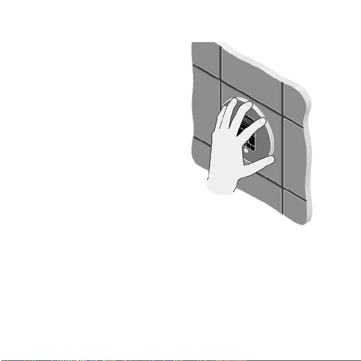
STEP 7
Diagram 6
Insure the mounting surface is clean an ry
as require for goo a hesion. Hol the
control with the LED isplay in the 12 o'clock
position an press the control against the wall
u ntil the a hesive sticks an hol s firmly.
Control may have to be supporte or secure
until the silicone fully cures an bon s.
7
DIAGRAM 6
Drawings for Ill strative P rposes Only.

Installing the Remote
Temperature Probe
(PN: MSTS)
The Remote Temperature Probe is require
when the iTempo or Tempo/Plus Controls
are installe outsi e the steam room.
The Remote Temperature
Probe (P/N MSTS) is for use with iTempo
an iTempo/Plus Controls only. Do not use
with any other controls. Do not use any
other temperature probe with the iTempo
an iTempo/Plus controls. Noncompatible
pro ucts may result in an inoperative con-
trol an a hazar ous con ition.
Install the iTempo or
iTempo/Plus controls accor ing to the in-
stallation instructions on pages 3-5. Failure
to o so may result in an inoperative con-
trol an a hazar ous con ition.
1. Determine the location of the Remote
Temperature Probe:
The Remote Temperat re Probe m st be
installed
:
a. On a vertical surface
b. 4-5 feet above the floor
c. in a location representative of the esire
steam bathing temperature. Locating the MSTS
near the steamhea or near irect steam emis-
sions may result in poor steamroom temperature
control.
d. The probe has an integral 30' cable. Insure that
the probe an /or steam generator are locate ac-
cor ingly.
2. Drill a 5/16 inch iameter hole in the wall. Do
not oversize or un ersize the hole. Clean area
thoroughly.
NOTE: The silicone supplie by Mr. Steam can be
use to meet a variety of sealing an gasketing. It
cures to silicone rubber an a heres to glass,
woo , metal, porcelain, ceramic tile, painte sur-
faces, many plastics an rubber. Surfaces must be
clean an ry. Apply thin layer of pro uct. Fit to-
gether an support if necessary. Allow excess mate-
rial to cure, then trim with a sharp bla e. Sealant
“skins” in 5 minutes, ries to touch in 1 hour. Fully
cures an bon s in 24 hrs.
3. Remove the knock-out from the steam
generator jacket as shown in Diagram 1.
4.
Insert the probe cable through the knock-out an
connect to the connector on the steam generator
printe circuit boar marke EXT TEMP as shown in
Diagram 1.
CAUTION
!
CAUTION
!
mr
.steam®Installation & Operating Instructions
______________________________________________________________
8
Este manual sirve para los siguientes modelos
1
Tabla de contenidos


