FAST ComTec MCCD Manual de usuario
MCCD
Eight output START trigger / master clock source
User Manual
© Copyright FAST ComTec GmbH
Grünwalder Weg 28a, -82041 Oberhaching
Germany
Version 1.1, November 3, 2020

2F ComTec GmbH

Copyright nformation
Copyright 2020 FAST ComTec GmbH,
D-82041 Oberhaching, Germany. All rights reserved.
This manual contains proprietary information; no part of it may be reproduced by any means without prior
written permission of FAST ComTec, Grünwalder Weg 28a, -82041 Oberhaching, Germany. Tel: ++49 89
66518050, FAX: ++49 89 66518040.
The information in this manual describes the hardware and the software as accurately as possible, but is
subject to change without notice.
F ComTec GmbH 3

Table of Contents
1 Introduction.................................................................................................................................................... 6
2 Hardware escription.................................................................................................................................... 7
2.1 Overview................................................................................................................................................ 7
2.2 Front Panel, Trigger Fan-out.................................................................................................................. 7
2.3 Rear Panel, Clock Fan-out..................................................................................................................... 8
3 Application: synchronized use of up to eight MCS8A multiscalers...............................................................10
4 Specifications............................................................................................................................................... 11
4F ComTec GmbH

Table of Figures
Fig. 2.1: The MCC Front Panel....................................................................................................................... 7
Fig. 2.2: Trigger input setting with JP1.............................................................................................................. 7
Fig. 2.3: The MCC Rear Panel....................................................................................................................... 8
Fig. 2.4 Jumpers JP2 for 50 Ohm Termination and JP3 for C/AC coupling....................................................8
Fig. 2.5: ivider setting .................................................................................................................................... 9
Fig. 3.1: Synchronized use of 8 MCS8A multiscalers.....................................................................................10
F ComTec GmbH 5

ntroduction
1 ntroduction
The Model MCC is a fast pulse distributor intended to be used with multiple MCS8A modules. It is also a
very good general-purpose pulse generator when multiple synchronized jitter-free signals are required. It
expands one common START signal to several synchronous starting MCS8A units. The introduced additional
time jitter is typical less than 0.075 ps rms. Output rise / fall time is 60 ps. The minimum pulse width is 90 ps.
It can operate up to 6 GHz periodic signal frequency.
In addition there is a synchronous clock source at the rear panel. It can supply up to 8 MCS8A units with a
common clock for synchronous operation of multiple MCS8A, providing up to 64 synchronized channels. It
has a clock input (TTL 3.3V, 10 to 120 MHz) to be distributed to the connected MCS8As. Termination can be
50 Ohm or 3 kOhm. AC or C coupling is selectable.
If no input signal is connected, by setting the jumper JP1 the internal 10 MHz clock source is fed to the
output connectors. The internal quartz oscillator can be replaced by an oven-stabilized oscillator (option
MCC OVX) or a highly stable Cs atomic clock (option MCC ATOM).
Also there is an optional binary divider (32 bit), which can reduce the external clock in binary steps. ivider
factor is set by internal jumpers.
6F ComTec GmbH

Hardware Description
2 Hardware Description
2.1 Overview
The MCC is a 8 output fast pulse driver with 60 ps rise time and a 8 output clock driver (TTL) with internal
reference clock or ext input.
2.2 Front Panel, Trigger Fan-out
The connectors at the front panel are for distributing one trigger signal from the TRG IN input to eight output
SMA connectors. Instead of an external trigger signal the internal (10 MHz) or external clock signal can be
fed to the output connectors by setting the internal jumper JP1, “Internal Trigger”, see Fig. 2.2.
F ComTec GmbH 7
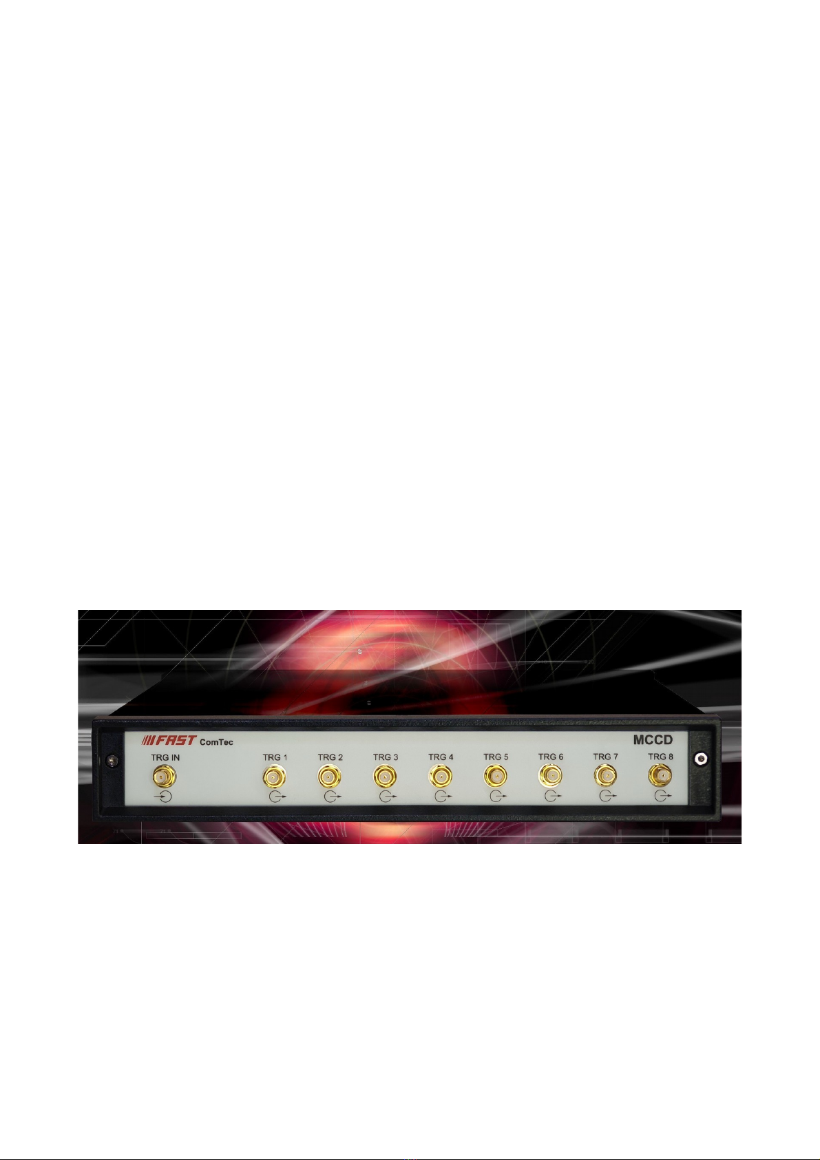
Fig. 2.1: The MCC Front Panel
Fig. 2.2: Trigger input setting with JP1

Hardware Description
2.3 Rear Panel, Clock Fan-out
At the rear panel a clock source (TTL 3.3V, 10 to 120 MHz) can be distributed from a BNC connector labeled
CLOCK IN to eight synchronous output signals at BNC connectors CLK1 - CLK8. Termination of the clock
input can be set to 50 Ohm or 3 kOhm with JP2. AC or C coupling is selectable with jumper JP3, see Fig.
2.4
A clock signal from an external source is automatically recognized. By two LE s it is indicated if the external
or the internal clock is used.
The internal quartz oscillator can be replaced by an oven-stabilized oscillator (option MCC OVX) or a highly
stable Cs atomic clock (option MCC ATOM).
Also there is an optional binary divider (32 bit), which can reduce the external clock in binary steps. ivider
factor is set by internal jumpers see Fig. 2.5.
8F ComTec GmbH
Fig. 2.3: The MCC Rear Panel
Fig. 2.4 Jumpers JP2 for 50 Ohm Termination and JP3 for C/AC coupling

Hardware Description
F ComTec GmbH 9
Fig. 2.5: ivider setting

Application: synchronized use of up to eight MCS8A multiscalers
3 Application: synchronized use of up to eight MCS8A
multiscalers
10 F ComTec GmbH
Fig. 3.1: Synchronized use of 8 MCS8A multiscalers
Tabla de contenidos


