fann 300 Series Manual de usuario
Series 300 LPLT Filter Press
Instruction Manual
Manual No. 207128, Revision G

207128 Revision G, September 2012 2
LPLT Filter Press Instruction Manual
©2012 Fann Instrument Company
Houston, Texas, USA
All rights reserved. No part of this work covered by the copyright hereon may be reproduced or
copied in any form or by any means (graphic, electronic, or mechanical) without first receiving the
written permission of Fann Instrument Company, Houston, Texas, USA.
Printed in USA.
The information contained in this document includes concepts, methods, and apparatus which may be
covered by U.S. Patents. Fann Instrument Company reserves the right to make improvements in
design, construction, and appearance of our products without prior notice.
FANN®and the FANN logo are registered trademarks of Fann Instrument Company in the United
States and/or other countries. All other trademarks mentioned in the operating instructions are the
exclusive property of the respective manufacturers.
Contact FANN
Phone
TELEPHONE: 281-871-4482
TOLL FREE: 800-347-0450
FAX: 281-871-4358
Mail
Fann Instrument Company
P.O. Box 4350
Houston, Texas, 77210 USA
Location
Fann Instrument Company
15112 Morales Rd Gate 7
Houston, Texas, 77032, USA
Online
www.fann.com
fannmail@fann.com

LPLT Filter Press Instruction Manual
207128 Revision G, September 2012 3
Table of Contents
1 Introduction ..............................................................................................................6
1.1 Document Conventions....................................................................................7
2 Safety.......................................................................................................................8
2.1 Safe Pressurization..........................................................................................8
3 Features and Specifications ...................................................................................10
4 Pressure Sources...................................................................................................11
4.1 Carbon Dioxide Pressure Source................................................................... 11
4.2 Nitrogen Cylinder Pressure Source................................................................13
4.3 Dead-Weight Hydraulic Pressure Source.......................................................14
4.4 External Pressure Source ..............................................................................15
5 Installation..............................................................................................................16
6 Standard Filter Press Test Procedures...................................................................17
7 Test Analysis.........................................................................................................20
7.1 References.....................................................................................................20
7.2 Results........................................................................................................... 20
8 Troubleshooting and Maintenance .........................................................................21
8.1 Cleaning.........................................................................................................21
8.2 Pressure Regulator Maintenance and Repair................................................. 21
8.3 Dead Weight Hydraulic Unit Maintenance...................................................... 25
9 Accessories............................................................................................................26
10 Parts List................................................................................................................27
11 Warranty and Returns............................................................................................ 38
11.1 Warranty ........................................................................................................38
11.2 Returns ..........................................................................................................38

LPLT Filter Press Instruction Manual
207128 Revision G, September 2012 4
List of Figures
Figure 3-1 Basic Filter Press Assembly ........................................................................10
Figure 4-1 CO2Cartridge Holder Assembly...................................................................12
Figure 6-1 Cell Assembly..............................................................................................19
Figure 8-1 CO2Pressure Assembly Drawing, P/N 208647............................................23
Figure 8-2 Nitrogen Regulator Assembly Drawing, P/N 208652.................................... 24
Figure 10-1 Series 300 LPLT Filter Press, Basic Assembly..........................................27
Figure 10-2 Filter Press with Air Hose...........................................................................28
Figure 10-3 Filter Press w/Regulator.............................................................................29
Figure 10-4 Filter Press w/ Nitrogen Regulator .............................................................30
Figure 10-5 Filter Press w/ Carbon Dioxide Pressure Assembly...................................31
Figure 10-6 Dead-Weight Hydraulic Assembly..............................................................32
Figure 10-7 Wall Mount Filter Press w/CO2Pressure Assembly ...................................33
Figure 10-8 Four Unit Filter Press w/Manifold...............................................................34
Figure 10-9 Six Unit Filter Press w/Manifold ................................................................. 35

LPLT Filter Press Instruction Manual
207128 Revision G, September 2012 5
List of Tables
Table 3-1 Basic Filter Press Assembly Specifications...................................................10
Table 9-1 Optional Equipment ......................................................................................26
Table 10-1 Filter Press, Basic Assembly, P/N 207127..................................................27
Table 10-2 Filter Press Assembly w/Air Hose, P/N 207173........................................... 28
Table 10-3 Filter Press Assembly w/Regulator, P/N 207174.........................................29
Table 10-4 Filter Press Assembly w/ Nitrogen Regulator, P/N 207223.......................... 30
Table 10-5 Filter Press w/ Carbon Dioxide Pressure Assembly, P/N 207224................31
Table 10-6 Dead-Weight Hydraulic Filter Press, P/N 207290........................................32
Table 10-7 Wall Mount Filter Press w/CO2Pressure Assembly, P/N 207503................33
Table 10-8 Four Unit Filter Press with Manifold, P/N 207785........................................ 34
Table 10-9 Six Unit Filter Press with Manifold, P/N 207673..........................................35
Table 10-10 CO2 Pressure Assembly, P/N 208647.......................................................36
Table 10-11 CO2Pressure Assembly w/ Top Cap, P/N 208648....................................36
Table 10-12 Accessories for CO2Pressure Assembly ..................................................36
Table 10-13 Pressure Regulator, P/N 208615 ..............................................................36
Table 10-14 Nitrogen Pressure Regulator, P/N 208652................................................37
Table 10-15 Accessories for Nitrogen Pressure Assembly, P/N 102177554 .................37

LPLT Filter Press Instruction Manual
207128 Revision G, September 2012 6
1 Introduction
Fann’s Series 300 LPLT Filter Press is used for measuring filtration and wall-
building properties of drilling fluids and cement slurries. The filtration rate is the
fluid loss measured in milliliters at ambient temperature and 100 psi (690 kPa)
through a special filter paper for 30 minutes. Wall-building characteristics are
demonstrated by the thickness and consistency of the filter cake (the residue)
deposited on the filter paper after 30 minutes. The filter cake is measured to the
closest 1/32 in. or the nearest millimeter.
The low pressure filter press assemblies described in this manual consist of the
following items:
filter cell mounted in a frame
pressure assembly and regulator
filter paper, the filtering medium
25 ml graduated cylinder, the filtrate receiver
The filter press cell body, top cap, and base cap are constructed of 303 stainless
steel.
The filtering medium is filter paper that has been especially hardened for filtrate
testing.
Pressure sources deliver the required pressure, 100 ± 5 psi (690 ± 35 kPa) and can
be any of the following:
compressed nitrogen or air in cylinders,
carbon dioxide gas cartridges,
high pressure air or water systems,
dead-weight hydraulic pressure assembly
Compressed oxygen should not be used as a pressure source.
Fire and explosion hazards exist when using oxygen.

LPLT Filter Press Instruction Manual
207128 Revision G, September 2012 7
1.1 Document Conventions
The following icons are used in this manual.
NOTE. Notes emphasize additional information that may be
useful to the reader.
CAUTION. Describes a situation or practice that requires operator
awareness or action in order to avoid undesirable consequences.
MANDATORY ACTION. Gives directions that, if not observed,
could result in loss of data or in damage to equipment.
WARNING! Describes an unsafe condition or practice that if not
corrected, could result in personal injury or threat to health.
ELECTRICITY WARNING! Alerts the operator that there is risk of
electric shock.
HOT SURFACE! Alerts the operator that there is a hot surface and
that there is risk of getting burned if the surface is touched.

LPLT Filter Press Instruction Manual
207128 Revision G, September 2012 8
2 Safety
Safe operation of filter presses requires that the laboratory technician or drilling
fluids engineer be familiar with the proper operation and potential hazards
associated with this equipment. For instance, if the filter cell or pressurization
equipment has a leak, then sample or pressurizing fluid could be released and cause
serious injury.
Several precautions that should be observed are described in this section.
2.1 Safe Pressurization
2.1.1 Gases
Always use nitrogen, carbon dioxide (CO2), or compressed air. Never connect
the LPLT Filter Press to oxygen, natural gas, or any other non-recommended
gas.
Compressed oxygen should not be used as a pressure source.
Fire and explosion hazards exist when using oxygen.
Nitrogen must be supplied from an approved nitrogen gas cylinder. Nitrogen
cylinders must be secured and meet all safety standards.
Carbon dioxide is normally supplied in small cartridges, which contain about
900 psi (6205 kPa) pressure. They are primarily used for field operations.
Do NOT allow carbon dioxide cartridges to be heated or exposed
to fire. They can explode if overheated.
If compressed air is used, its maximum pressure should not exceed 150 psi
(1035 kPa) at the regulator inlet.

LPLT Filter Press Instruction Manual
207128 Revision G, September 2012 9
2.1.2 Pressure Regulators
Maintain pressure regulators in good condition. Never use oil on pressure
regulators.
Pressurization systems that leak should be repaired or replaced.
Gauges, fittings and hoses should be kept in good condition and leaks should be
corrected.
Periodically test the safety relief valves on the pressurization manifolds to
verify they will relieve if excessive pressure should occur. Never plug or bypass
these safety valves.
When pressurizing the cell, always make sure that the regulator is closed (i.e.,
Tee screw backed all the way out, counterclockwise). Then open the supply
pressure, and adjust the regulator.
Do NOT attempt to pressurize higher than 100 psi (694 kPa).
Follow the pressurizing procedures in Section 4.
When depressurizing, first shut off the supply pressure. Then bleed the system
of pressure, and back out the regulator Tee screw (turn counterclockwise),
following the procedures in Section 4.

LPLT Filter Press Instruction Manual
207128 Revision G, September 2012 10
3 Features and Specifications
This filter press is used in a static filtration test to measure fluid loss and filter cake
characteristics of drilling fluids.
The basic filter press assembly consists of the filter press unit and accessories,
listed in Section 10. See Figure 3-1.
The specifications for the LPLT Filter Press are listed in Table 3-1.
Table 3-1 Basic Filter Press Assembly Specifications
Category
Specification
Working Pressure
100 psi (690 kPa)
Filtering Area
7.1 in2 (45.8 cm2)
Dimensions (Width x Depth x Height)
9 x 9 x 20 inches
22.86 x 22.86 x 50.8 centimeters
Weight
15 lb (6.8 kg)
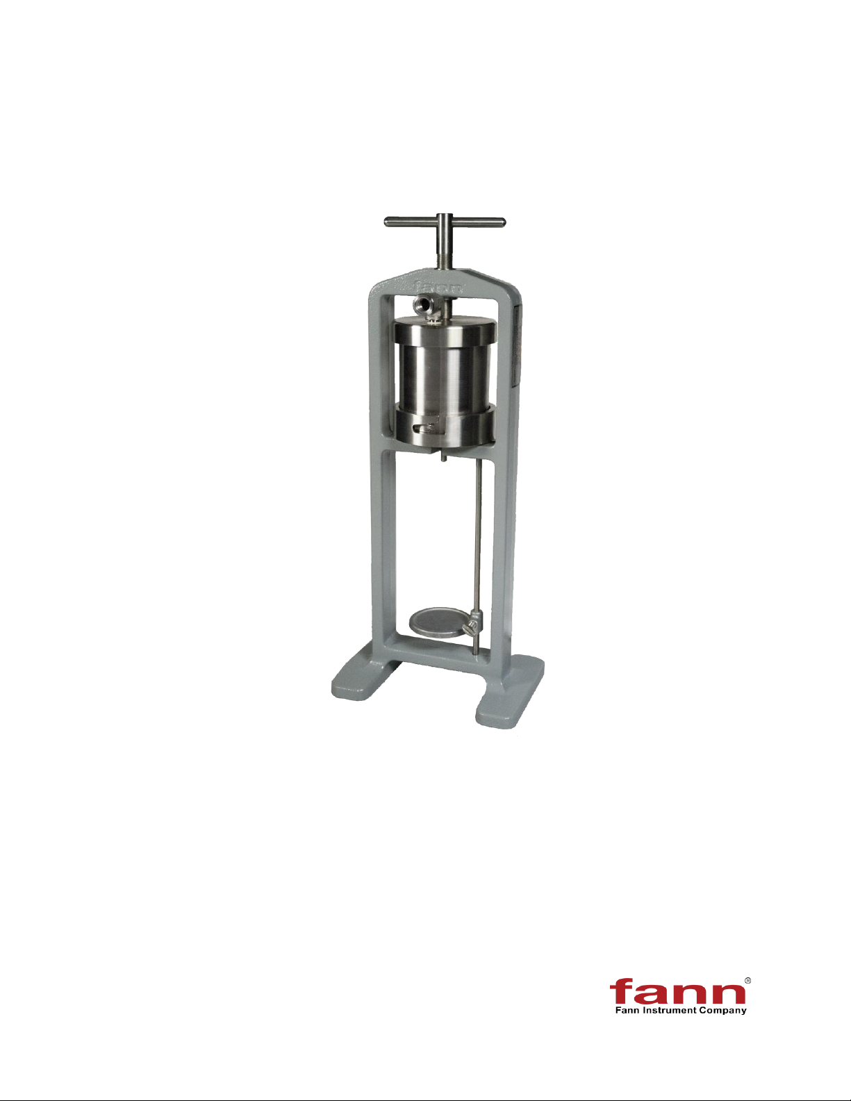
Figure 3-1 Basic Filter Press Assembly
T-screw
Support Rod
Thumb Screw
Cell Body
Pressure Inlet
Support for graduated
cylinder
Frame
Top Cap
Base Cap
Tabla de contenidos


