fafnir ME 6 Series Guía

Technical Documentation
FAFNIR GmbH • Schnackenburgallee 149 c • 22525 Hamburg • Tel.: +49 / 40 / 39 82 07–0 • Fax: +49 / 40 / 390 63 39
ME 6 …
Overfill prevention sensor tester
Version: 4
Edition:
2019-04
Art. no.: 350227

I Contents
Table of contents
1Overview .................................................................................................... 1
2Safety instructions .................................................................................... 2
3The ME 6 ... overfill prevention sensor testing device ......................... 3
3.1 Design and construction .................................................................................................................3
3.2 Function .................................................................................................................................................4
3.3 Scope of delivery................................................................................................................................5
4Operation ................................................................................................... 6
4.1 Fundamentals ......................................................................................................................................6
4.2 Start-Up .................................................................................................................................................8
4.2.1 Basic settings .......................................................................................................................................9
4.3 Testing the Overfill Prevention Sensor.....................................................................................11
4.3.1 Heating-up time ...............................................................................................................................13
4.3.2 Switch-off time..................................................................................................................................13
4.3.3 QSS Code (ME 6 P) ..........................................................................................................................15
4.4 Power saving (stand-by) mode and reactivation..................................................................15
4.5 Settings ................................................................................................................................................16
4.5.1 Country selection .............................................................................................................................17
4.5.2 Date and time....................................................................................................................................17
4.5.3 Backlight ..............................................................................................................................................18
4.5.4 Touch screen calibration................................................................................................................18
4.5.5 QSS code identifiers........................................................................................................................20
4.5.6 Readings archive...............................................................................................................................21
4.5.7 Delete readings.................................................................................................................................21
4.5.8 Resetting to factory settings........................................................................................................22
4.6 Power supply......................................................................................................................................22
4.6.1 Changing the rechargeable batteries .......................................................................................22
4.6.2 Regular charging of the rechargeable batteries necessary ..............................................23
5PC software..............................................................................................24
5.1 Driver installation .............................................................................................................................24
5.2 Starting the ME 6 Software...........................................................................................................24
5.2.1 Settings ................................................................................................................................................24
5.2.2 Records ................................................................................................................................................26

Contents II
6Technical Data .........................................................................................27
7List of figures...........................................................................................28
8List of tables.............................................................................................28
9Annex........................................................................................................29
9.1 EC Declaration of Conformity......................................................................................................29
9.2 EC Type Examination Certificate (ATEX) ..................................................................................30
9.3 Instructions.........................................................................................................................................32
© Copyright:
Reproduction and translation are permitted only with the written consent of FAFNIR GmbH. FAFNIR
GmbH reserves the right to carry out product alterations without prior notice.

Page 1/33 Design and construction
1Overview
Testing obligations in accordance with §§ 15 and 16 of the German Indus-
trial Safety Regulations (BetrSichV) and § 1 of the German Regulations on
Equipment Handling Substances Hazardous to Water (WasgefStAnlV). In
other countries, the corresponding national rules and regulations must be
observed.
When in operation, storage facilities for static tanks, filler points, petrol sta-
tions, airport refuelling equipment, and their components, e.g. overfill
prevention sensors, must be tested by an approved inspection agency prior
to commissioning, re-commissioning (after modifications subject to testing)
as well as repeatedly at specific testing intervals.
The system parts, e.g. overfill prevention sensors, must be tested by the op-
erator or an authorised person as required by the manufacturer's operating
instructions at regular intervals.
The ME 6 … overfill prevention sensor testing device guarantees optimal and safe test-
ing in accordance with prEN 13616-2 …
Three different types of these testing devices are available; they differ in the nature of
the application and the medium which is to be monitored:
•The ME 6 is used to test overfill prevention sensors without product coding.
•The ME 6 P is used to test overfill prevention sensors with product coding
in accordance with Quality Assurance systems (QSS).
•The ME 6 F is used to test overfill prevention sensors in LPG tanks.
In the following sections you will be guided by means of a detailed description
through the installation and commissioning of the ME 6 … overfill prevention sensor
testing device.
The ME 6 … overfill prevention sensor testing device may only be supplied
with power by 4 pcs NiMH rechargeable batteries (type AA 1.2 V, 2000 mAh).

Design and construction Page 2/33
2Safety instructions
The safety instructions in this manual are marked as follows:
If you do not comply with the safety instructions, there is a risk of accident,
or the device/system may be damaged.
Useful tips and information in this manual that should be observed appear
in italics and are identified by this symbol.
The ME 6 … overfill prevention sensor testing device is used to test overfill prevention
sensors in storage tanks. The testing device must be used exclusively for this purpose.
The manufacturer accepts no liability for any form of damage resulting from improper
use.
The ME 6 … overfill prevention sensor testing device has been developed, manufac-
tured and tested in accordance with the latest good engineering practices and
generally accepted safety standards. Nevertheless, hazards may arise from its use. For
this reason, the following safety instructions must be observed:
Do not change or modify the testing device or add any equipment without
the prior consent of the manufacturer.
The operation and maintenance of the testing device must be carried out
by expert personnel only. Specialised knowledge must be acquired by regu-
lar training.
Operators, installers and service technicians must observe all applicable
safety regulations. This also applies to any local safety and accident pre-
vention regulations which are not stated in this manual.
The manufacturer accepts no liability for any other batteries than the
required NiMH rechargeable batteries, see chapter 6, Technical Data.
Charging standard batteries instead of rechargeable batteries result in the
risk of fire or explosion.

Page 3/33 Design and construction
3The ME 6 ... overfill prevention sensor testing device
3.1 Design and construction
The ME 6 ... overfill prevention sensor testing device is used to test overfill prevention
sensors in accordance with prEN 13616-2. In order to do this, the testing device is
equipped with a socket coupler on a flexible spiral cable.
The testing device is operated by a touch screen.
Readings which has been saved can be transferred to a PC/laptop and archived by
means of software and the USB socket.
The testing device is powered by 4 pcs NiMH rechargeable batteries. These can be
replaced by the user. The batteries can be charged by a plug-in power supply or a
PC/lap top via the USB socket.
A toggle switch is used to move between the two operating modes Measurement and
USB connection/charging.
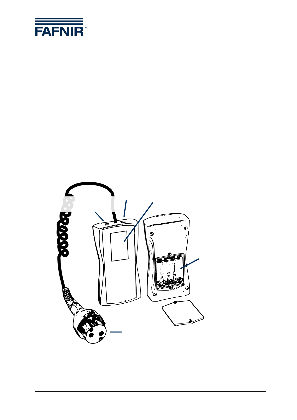
Figure 1: The ME 6 ... overfill prevention sensor testing device
USB socket
Type B
Battery compartment
Overfill prevention sensor coupling socket
Toggle switch
Measurement / USB
Touchscreen

Function Page 4/33
3.2 Function
The overfill prevention sensor is heated by the intrinsically safe electric current of the
ME 6 ... overfill prevention sensor testing device. The heating-up time needed is meas-
ured, assessed and presented on the screen. The switch-off time is treated in the same
way. The QSS coding is captured and also displayed (ME 6 P).
As the testing device has an intrinsically safe output circuit, it can be used for testing
all overfill prevention sensors approved by prEN 13616-2. The testing device itself must
be operated outside the Ex area. The type 903 socket coupler needed for the connec-
tion to the overfill prevention sensor is equipped with an appropriate length of cable.
The testing device must be equipped with a FAFNIR socket coupler type AS 903 for
checking the product identification.
The testing device is fitted with 4 pcs. NiMH rechargeable batteries. These batteries are
charged with the plug-in power supply via the USB socket or with the USB host of a
PC/laptop. They can only be charged when in USB mode. Depending on the nominal
capacity of the batteries, it takes about 10 hours to charge them. The batteries can be
freely exchanged.

Page 5/33 Scope of delivery
3.3 Scope of delivery
•The ME 6 ... overfill prevention sensor testing device with connected coupling
cable (with product identification, without product identification, or LPG)
•USB cable type A/B
•4 pcs NiMH rechargeable batteries (type AA 1.2 V, 2000 mAh), plugged in
or separate
•Technical Documentation
Figure 2: Scope of delivery in carrying case as a set (e.g. ME 6 P)

Fundamentals Page 6/33
4Operation
4.1 Fundamentals
The ME 6 ... overfill prevention sensor testing device is operated by a Touchscreen;
operations are activated by touching special activation fields. The user is generally
guided by icons or informative items of short text with the result that it is quite evident
in the individual screens which functions are triggered by the various activation fields.
The activation fields which regularly recur are listed below.
Confirmation, Activity successful, Amendments accepted
Refusal, Unsuccessful, Abort without amendments, Delete
Return to the previous screen
Input of figures
Figure 3: Activation fields of the graphical user guidance
In this manual important activation fields are highlighted by a fingertip in symbolic
form.
Excessive pressure can damage the screen. Gently touching the screen is
sufficient to operate it.
If no reaction is produced, the touch screen is perhaps decalibrated. In this
case, all that is needed to start the calibration process is to touch the screen
with a finger for about 5 seconds.

Page 7/33 Fundamentals
When in the main screens, the date, time, memory occupancy, and battery status is
indicated in the upper line of the screen.
<Measuring range data storage over 50% full
<Batteries about 1/3 discharged
<Memory almost empty
<Batteries being charged
<Memory almost full
<No batteries inserted; testing device being powered via the
USB socket
Figure 4: Status display
Este manual sirve para los siguientes modelos
3
Tabla de contenidos
Otros manuales de Equipo de prueba de fafnir
Manuales populares de Equipo de prueba de otras marcas

SMART
SMART KANAAD SBT XTREME 3G Series Manual de usuario

Agilent Technologies
Agilent Technologies BERT Serial Manual de usuario

Agilent Technologies
Agilent Technologies N3280A Manual de usuario

Vernier
Vernier Go Direct Voltage Manual de usuario

Lifeloc
Lifeloc R.A.D.A.R. Manual de usuario

Fluke
Fluke T5-600 Instrucciones de funcionamiento e instalación