2
Contents
1GENERALINFORMATION………………………………………………………………………………………………4
1.1Warnings………………………………………………………………………………………………………….4
1.2Symbols……………………………………………………………………………………………………………4
1.3SafetyInstructions…………………………………………………………………………………………...4
2TECHNICALFEATURES…………………………………………………………………………………………………..6
2.1TypicalSchematicPrinciple(AllTopConnections………………………………………………6
2.2Connectionconfigurations…………………………………………………………………………….…7
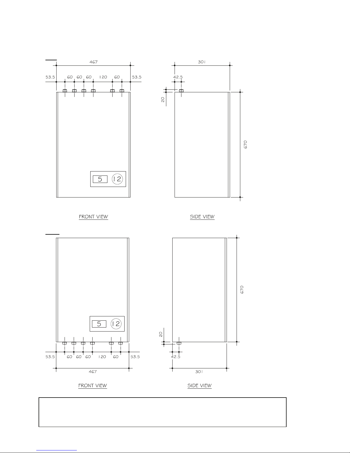
2.3Dimensions……………………………………………………………………………………………………...10
2.4TechnicalFeatures…………………………………………………………………………………………...14
3INSTALLATION………………………………………………………………………………………………………………15
3.1Recommendedhandlingprocedure………………………………………………………………….15
3.2ModuSatTPpositioning……………………………………………………………………………………15
3.3ChecksbeforeconnectingtheModuSatTP……………………………………………………….15
3.4HydraulicConnections………………………………………………………………………………………17
3.5UseofPre‐installationRig………………………………………………………………………………..18
3.6WallFixing……………………………………………………………………………………………………….19
3.7PressureIndependentControlValve(PICV)Adjustment……………………………………21
4PRIMARYANDSECONDARYCIRCUIT…………………………………………………………………………….24
4.1Watertreatment……………………………………………………………………………………………..24
4.2Cleaning…………………………………………………………………………………………………………..24
4.3Precautions………………………………………………………………………………………………………25
4.4Bionibal……………………………………………………………………………………………………………26
4.5FlushingBypass………………………………………………………………………………………………..27
5ELECTRICCONNECTIONS……………………………………………………………………………………………….28
5.1ModusatWiringConnections……………………………………………………………………………29
5.2ModuSatConnectionBoard(Visibleoncethecoverisremoved)……………………….31
5.3Roomcontrollerconnections…………………………………………………………………………….32
5.4TypicalModuSatElectricWiringDiagram(SingleRoomController)………………….34
5.5TypicalModuSatElectricWiringDiagramwith2ZoneControl
(2RoomControllers)…………………………………………………………………………………………35