9
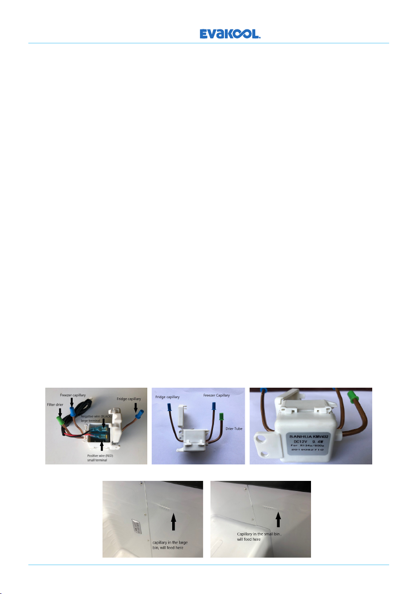
SOLENOID: Sanhua KMV432. 12 Volt 9.4W solenoid. (Part No: SOLENOID-A)
These fridges have 2 separate refrigeration systems and one compressor. The solenoid is
used to direct liquid refrigerant at the drier to the circuit that requires refrigeration. The
electronics sense when either the small or large bin needs cooling and sends a 12 Volt
pulse to the solenoid, either a positive or negative pulse is required to change from one
side to another.
To Test: To see if the solenoid is switching, first turn the refrigerator on, Room 2 (small bin)
will start to refrigerate, feel where the capillary enters the evaporator plate (image 4 & 5).
When it starts to feed, switch OFF that bin (see page 5), the solenoid will then switch over
to the other side, feel where the capillary enters the evaporator if it starts to feed you know
that the solenoid is switching and capillaries are clear, so the issue may be in the PCB
controlling the solenoid.
Warning: Before removing the old solenoid carefully mark or identify the capillaries so
they go back into the correct sides of the solenoid, failing to do so will result in erratic
temperature fluctuations and incorrect temperatures in both sides. Wrap the body of the
solenoid in wet rags before welding, failing to do so will melt the internals and stop the valve
from switching.
To Replace: Once identified, with the use of a capillary cutters, cut o both capillaries,
open the top cap and remove the wires small terminal (red) and large terminal (black),
un-sweat the drier from the condenser as it needs to be replaced, now the system is
opened (image 1). To install a new solenoid, insert the capillaries into their correct tubes
and push in all the way (there is a small dimple in the receiving copper tube to ensure
the capillary cannot be pushed in to far). Unpack the new drier and insert the large pipe
on the solenoid into the exit opening of the drier then insert the discharge tube from the
condenser into the entry opening of the drier.
DOWN UNDER SERIES
Image 1 Image 2 Image 3
Image 4 Image 5