
EUTHANEX SmartBox M1TSFF2C-FM Manual de usuario

Auto CO2System
Models M1TSFF2C-FM
4/21/2020
877-559-0159 Toll Free Euthanex Corp. / E-Z Systems Inc.
610-559-0159 Phone P.O. Box 3544
610-821-3061 Fax Palmer, PA 18043
www.euthanex.com [email protected]m

2
TABLE OF CONTENTS
Disclaimer ____________________________________ 3
System Overview _______________________________ 4
Saftey________________________________________ 5
System Setup __________________________________ 6
Operating the System ___________________________ 13
Changing Operating Specifications _________________ 20
Troubleshooting _______________________________ 30
EMC / EMI.
This equipment has been tested and found to
comply with the limits for a Class A Equipment,
pursuant to part 15 of the FCC rules.
IEC 61326-1:2005 / EZ 61326-1:2006

3
DISCLAIMER
THIS MANUAL MUST BE READ BEFORE SETTING UP AND OPERATING THE AUTO CO2
SYSTEM. The user should be thoroughly familiar with the contents of this manual prior to using the
system with animals. Only technicians that are properly certified should operate the Auto CO2System.
The user/owner of this equipment shall have the sole responsibility for any damage or injury resulting
from operation that is not in accordance with the authorized instructions. This includes, but is not limited
to, operating the equipment outside of recommended safety levels, variation from specified operating
instructions and not following standard laboratory safety procedures when working with anesthetic
agents and volatile compressed gases.
The system and its components must only be modified or repaired by Euthanex-authorized service
technicians. Improper modification or repair may result in danger to personnel, harm or death to animals
and/or equipment damage. The user/owner of this equipment shall have the sole responsibility for any
damage or injury resulting from improper maintenance and repair that is not done by authorized
maintenance and repair personnel.
Parts that have failed, in whole or in part, exhibit excessive wear, are contaminated or are otherwise at
the end of their useful life, should not be used and should be replaced with parts supplied by Euthanex
Corporation. Tampering with the controller unit by unauthorized personnel voids all warranties and
specifications. The manufacturer assumes no responsibility for any malfunction or failure of the unit if
tampering is suspected.

4
SMARTBOX FIXED FLOW SYSTEM OVERVIEW
The SmartBox Fixed Flow M1-TSFF Auto CO2System is an advanced automated euthanasia unit that
has been developed specifically for euthanizing small rodents. The system incorporates three key
components, the SmartBox Fixed Flow Controller, the M1 Chamber and the Exhaust Blower. The
system works with preset timings that assure humane and efficient levels of CO2. Gas flow rate is set at
the source (fixed flow), while the timings are controlled by the automated controller unit. The
controller does not impact the flow rate, but delivers gas at the rate that is output by the source.
The TSFF Controller operates in preset automated stages:
1) Gas Flow: Flow rate is set to conform to the AVMA guidelines for humane
euthanasia. CO2flows into the top chamber and anesthetizes the animals with minimal
stress. While the animals are anesthetized, the gas flow continues and increases the
chamber’s CO2concentration to euthanizing level.
2) Dwell Time: Gas flow shuts off and the chamber remains fully charged to assure
euthanasia of all animals.
3) Optional 2nd Gas Charge can be set for each species registered in system.
4) Evacuation Time: Onboard blower evacuates CO2out of the chamber and into the in-house
exhaust system and then shuts off after the chamber is fully purged. All gas is completely
purged from the chamber, making it safe for personnel to remove cages at the completion
of the cycle.

5
The lightning flash with an arrowhead
symbol within an equilateral triangle, is
intended to alert the user to the presence of
uninsulated "dangerous voltage" within the
product's enclosure that may be of sufficient
magnitude to constitute a risk of electric shock to
persons.
1. Read these instructions.
2. Keep these instructions.
3. Heed all warnings.
4. Follow all instructions.
5. Do not use this unit near water.
6. Do not clean by spraying liquid directly onto
unit.
7. Do not block any ventilation openings.
Install in accordance with the manufacturer's
instructions.
8. Do not install near any heat sources such
as radiators, heat registers, stoves, or other
unit that produce heat.
9. Do not defeat the safety purpose of the
polarized or grounding-type plug. A
polarized plug has two blades with one
wider than the other. A grounding type plug
has two blades and a third grounding
prong. The wide blade or the third prong
are provided for your safety. If the provided
plug does not fit into your outlet, consult an
electrician for replacement of the obsolete
outlet.
10. Protect the power cord from being walked
on or pinched particularly at plugs,
convenience receptacles, and the point
where they exit from the unit.
11. Unplug this unit during lightning
storms or when unused for long periods of
time.
12. Refer all servicing to qualified service
personnel. Servicing is required when the
unit has been damaged in any way,
such as power-supply cord or plug is
damaged, liquid has been spilled or objects
have fallen into the unit, the
unit has been exposed to rain or
moisture, does not operate normally, or has
been dropped.
The exclamation point within an equilateral triangle is
intended to alert the user to the presence of important
operating and maintenance (servicing) instructions in
the literature accompanying the product.
Warning!
•To reduce the risk of fire or electric shock,
do not expose this unit to rain or
moisture.
•Use line cord supplied with the product.
•Be advised that different operating voltages
require the use of different types of line
cord and attachment plugs. The unit was
shipped with the requested plug. If the
installation requirements change please
contact us for the correct plug.
•This equipment should be installed near the
socket outlet and disconnection of the device
should be easily accessible.
•Do not install in a confined space.
•Do not open the unit - risk of electric shock
inside.
Caution: You are cautioned that any change or
modifications not expressly approved in this
manual could void your authority to operate
this equipment.
Service
•There are no user-serviceable parts inside.
•All service must be performed by qualified
personnel.
Voltage
100-240 v ac 50-60hz 5 amp Max (auto
select)
Pressure
175 psi max to inlet
Temp
0 to 40°C <> 10 to 85% RH (no
condensation)
SYSTEM SETUP
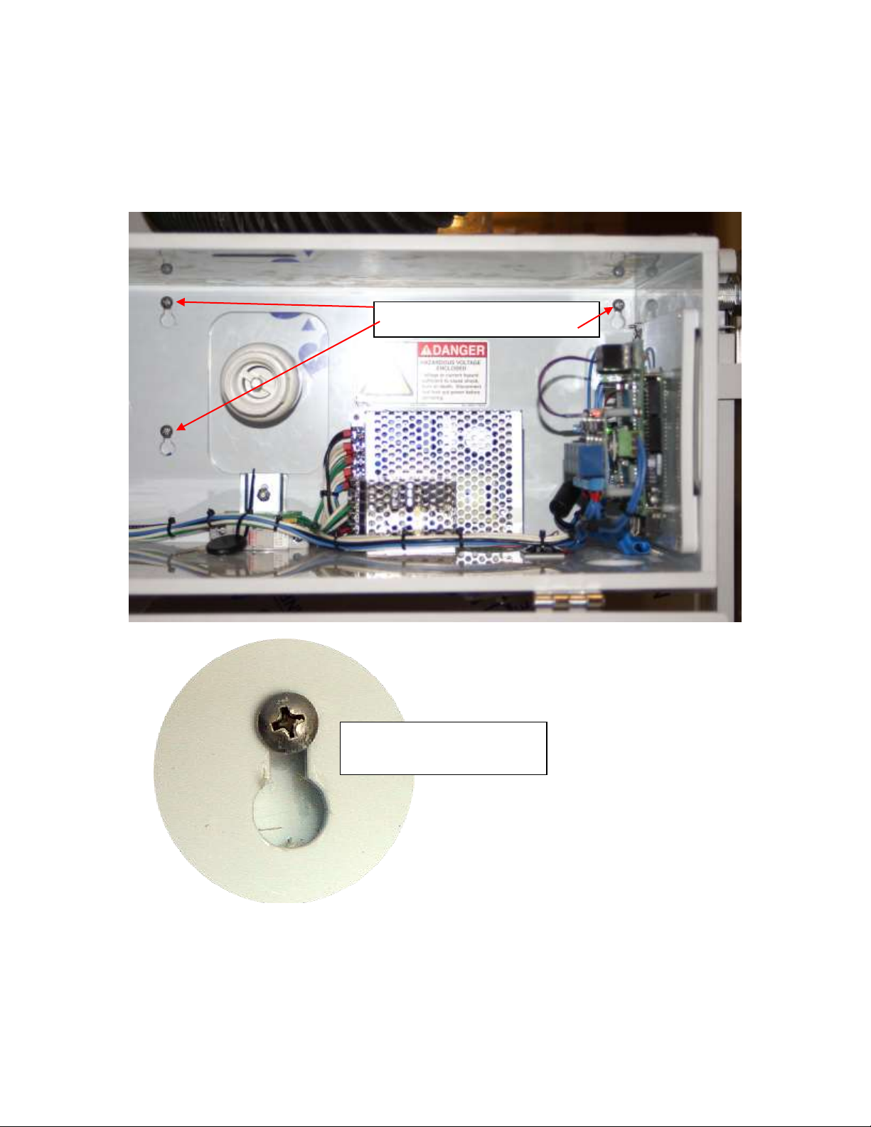
1) The SmartBox controller is attached to the top M1 chamber utilizing the four keyholes on the back
of the controller. Note: The chamber door must be opened to hang controller.
Align the keyholes with the four screws on the left side of the chamber. Push in and slide down to
secure. The screws may be tightened for permanent mounting.
Screw mounts on chamber side
Controller keyhole mounted
on chamber screw

7
2) On the bottom of the SmartBox side control box is a brass CO2input fitting that must be connected
to the CO2supply. For Tank supply gas see step #9 and for house see step #12.
3) On the side of the M1 chamber is a brass CO2input fitting that must be connected to the CO2supply
line that is coming out of the side control box. Do this for each chamber in the system.
CO2Input Hose
CO2Input Connection
ConnCpmme.
CO2Input Fitting

8
4) TSFF-2C/3C Models Only are equipped with the ESC safety lock microswitch that allows the second
and third chamber to lock when in use. Use the four pin connector to attach to the back of the ESC.
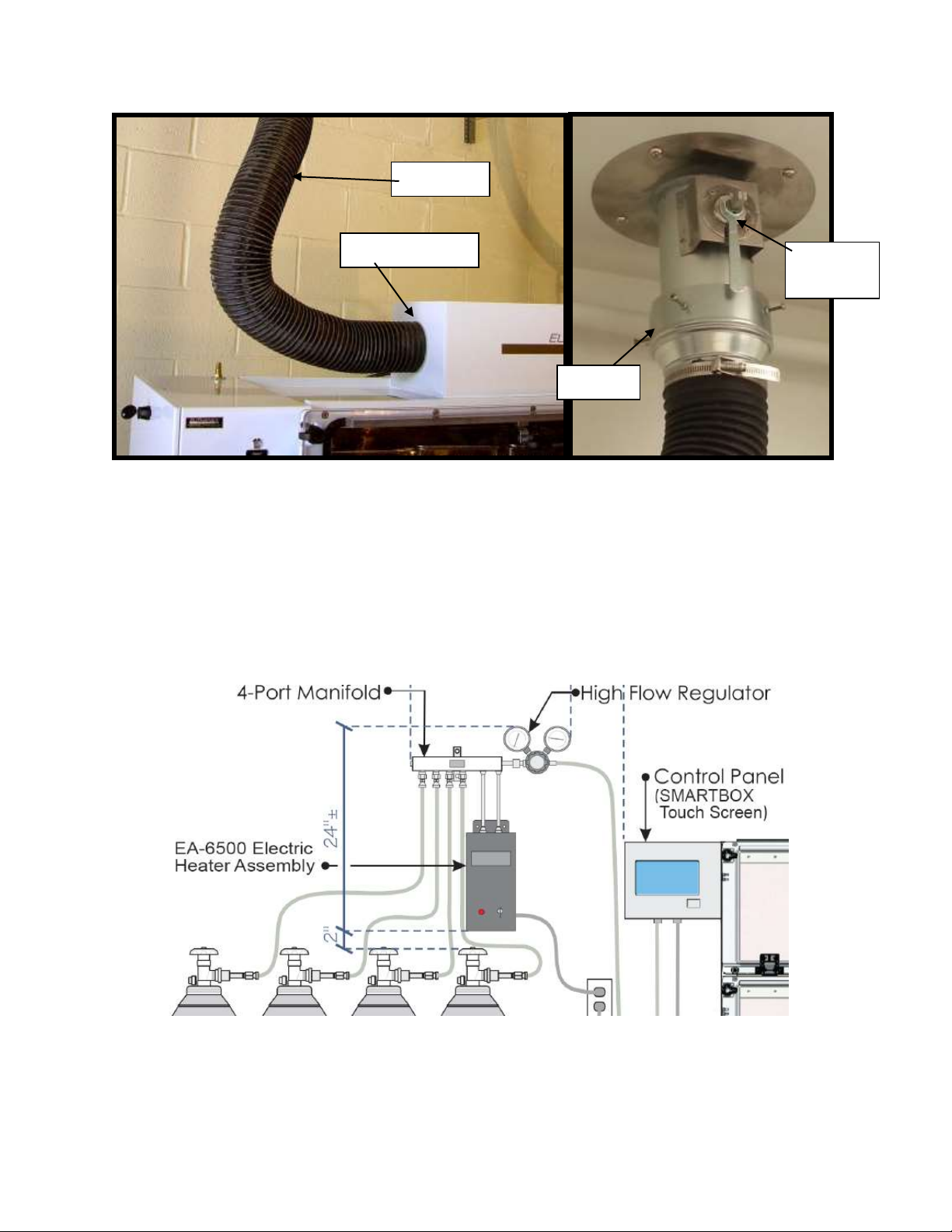
5) Rest the exhaust blower on top of the chamber. The large 4” exhaust hose must be on left and the 1”
intake hose on the right.
6) Attach the 1” intake hose from the blower to the “CO2Out” on the right side of top chamber. The
clamp connector fastens by pulling the two clamps away from chamber. Do this for each chamber in
the system.
Connect the data cable 15 pin connector that is from the side control box to the female 15 pin
connector on the exhaust blower box next to the power
CO2Input to Exhaust Blower
CO2Output from Chamber
9
7) Attach the 4” exhaust hose from the blower to the in-house exhaust system. For facilities without
in-house exhaust, drop the exhaust hose to the floor, allowing the CO2to dissipate away from
personnel.
Euthanex also offers a flat wall plate thimble for adapting to flat return grates.
8) For hose supplied gas go to step #10
9) EA-6500 Install Instructions
The unit should be mounted above the top of the tanks as seen above. The power must be within 6 ft of
the mounting location.
Tools required: level, marker, 1/4 drill bit for concrete or drywall
Exhaust Blower
4” Exhaust
House
Damper
Thimble

10
A. Hold assembly firmly against the wall where you would like to mount your manifold.
B. Use level to ensure the manifold is level against the wall
C. Use a marker or pencil to scribe the four (4) holes, 2 located on the manifold bracket and 2
located on the regulator bracket.
D. Remove the assembly to expose scribe marks
E. Use a 1/4” drill bit (not included) and drill the four (4) holes
F. Insert the four (4) plastic anchors (included) and press firmly into the wall
G. Hold the assembly against the wall and line us the predrilled holes
H. Use a #2 screwdriver and screw the four (4) screws through the plate into the anchors
Tabla de contenidos
Otros manuales de Equipos industriales de EUTHANEX


