Euroheat IN1174 Manual de usuario

© EUROHEAT DISTRIBUTORS (H.B.S) LTD. April 2008 Operating Instructions Part number IN1174 Ed. B
1
Operating Instructions
for the
Multifunction
Remote Control
IN1174
Euroheat Distributors
(H.B.S.) Ltd.,
Unit 2, Court Farm
Business Park,
Bishops Frome,
Worcestershire,
WR6 5AY.
Thermic Distribution
Europe SA,
B-5660 Frasnes-lez-
Couvin,
Belgium.

© EUROHEAT DISTRIBUTORS (H.B.S) LTD. April 2008 Operating Instructions Part number IN1174 Ed. B
2
WARNING
Important Safety Information
Read this manual thoroughly prior to installing, programming or operating this remote control.
This remote control system requires three (3) AAA and four (4) AA alkaline batteries to power the transmitter
and receiver. This remote control system should only be used as described in this manual. Any other use is not
recommended and will void the warranty.
NEVER LEAVE THE TRANSMITTER HANDSET ON TOP OF THE APPLIANCE AS IT MAY DAMAGE BOTH
THE HANDSET AND THE SURFACE OF THE APPLIANCE.
NOTE
Due to the sensitive temperature monitoring components in the transmitter, it is necessary to allow the transmitter
to stabilize to room temperature before accurate room temperatures are displayed. If the transmitter is activated
from a severe cold condition, allow 15 minutes for accurate temperature readings to appear on the LCD.
Installation
Turn appliance OFF and allow to cool before installing or servicing. Any modification of components will void the
warranty and may cause a fire hazard.
Contents
Installation ................................................................................................................... 2
Contents of Kit .............................................................................................................. 3
Features and Specifications........................................................................................... 3
Fitting the Remote Control Motor from Remote Kit: MS9174........................................ 4
Fitting the Remote Control Motor from Remote Kit: MS9219........................................ 5
Batteries ....................................................................................................................... 6
Reciever Plugs............................................................................................................... 8
Testing the Receiver’s Motor Operation ........................................................................ 9
Setting the Display to Show Temperature................................................................... 10
The Temperature Display ............................................................................................ 11
Low Battery................................................................................................................. 11
Setting the Auto Temperature .................................................................................... 12
Child Lock.................................................................................................................... 13
If More than One Remote System Within the Same Property ..................................... 14
Optional Transformer .................................................................................................. 15

© EUROHEAT DISTRIBUTORS (H.B.S) LTD. April 2008 Operating Instructions Part number IN1174 Ed. B
3
Thermostatic HI/LO Remote Control.
This hi/lo remote control system provides a safe, reliable and user-friendly remote control.
The remote can be operated in “Manual” mode by pressing the “ ” button to raise the firing rate or the “ ”
button to reduce the firing rate.
When the “Auto” button is pressed two temperatures are displayed. The upper one, showing the ambient
temperature, and the lower one, showing the set temperature. By pressing the “ ” and “ ” buttons the
set temperature can be raised or lowered. In the “Auto” mode the firing rate of the stove will be increased or
lowered to achieve an ambient temperature matching that of the set temperature.
The initial movement will be made within five seconds and thereafter at fifteen minute intervals.
The unit will only instigate four consecutive movements in either direction, which will take the stove to its
maximum or minimum firing rate.
Description Qty
Transmitter (Handset) 1
Battery Alkaline AAA
(for transmitter) 3
Receiver (Assembly)
consists of:
Receiver Box
L Bracket with ON/HI OFF/LO Buttons
1
Battery Alkaline AA (for Receiver) 4
Wall Holster 1
Wall Holster Screws 2
Raw Plugs 2
Velcro 1
Installation Instructions 1
Motor with leads and plug 1
Contents of Kit
Features and Specifications
Contemporary ergonomic style transmitter with large LCD display
Back lit LCD display
Battery powered transmitter and receiver
Easy access front battery door
Preprogrammed for quick installation
Low battery indication
Child proof lockout
Thermal shutdown and out of range shutdown on transmitter
Quick disconnect wiring assembly
Reset switch
Carefully inspect the contents for shipment
damage. If any parts are missing or damaged,
immediately contact the dealer from whom
you purchased the kit. Do not attempt to install
any part of the kit unless all parts are in good
condition.
+
+
-
-

© EUROHEAT DISTRIBUTORS (H.B.S) LTD. April 2008 Operating Instructions Part number IN1174 Ed. B
4
Fitting the Remote Control Motor from Remote Kit: MS9174
At the rear of the appliance you will see the
motor fitting bracket. This incorporates a magnet
and the mechanism friction plate.
The friction plate is hinged. To fit the motor this
friction plate needs to be detached from the magnet
and swung to the left.
The motor can now be slipped into place.
The magnet retains the motor.
Connect the electrical lead to the receiver box and
place the receiver box in its holder.

© EUROHEAT DISTRIBUTORS (H.B.S) LTD. April 2008 Operating Instructions Part number IN1174 Ed. B
5
Fitting the Remote Control Motor from Remote Kit: MS9219
The friction plate is hinged. To fit the motor this friction plate needs to be detached from the magnet and swung
downwards.
The motor can now be slipped into place. The magnet retains the motor.
Connect the electrical lead to the receiver box and
place the receiver box in its holder.
Remove the four screws
securing the facia plate
and the single grub screw
securing the air direction
lever knob.
Slip the motor in from the side, when over the retaining
bracket rotate to the right and lower into place. The motor
is retained by the magnet.

© EUROHEAT DISTRIBUTORS (H.B.S) LTD. April 2008 Operating Instructions Part number IN1174 Ed. B
6
Batteries
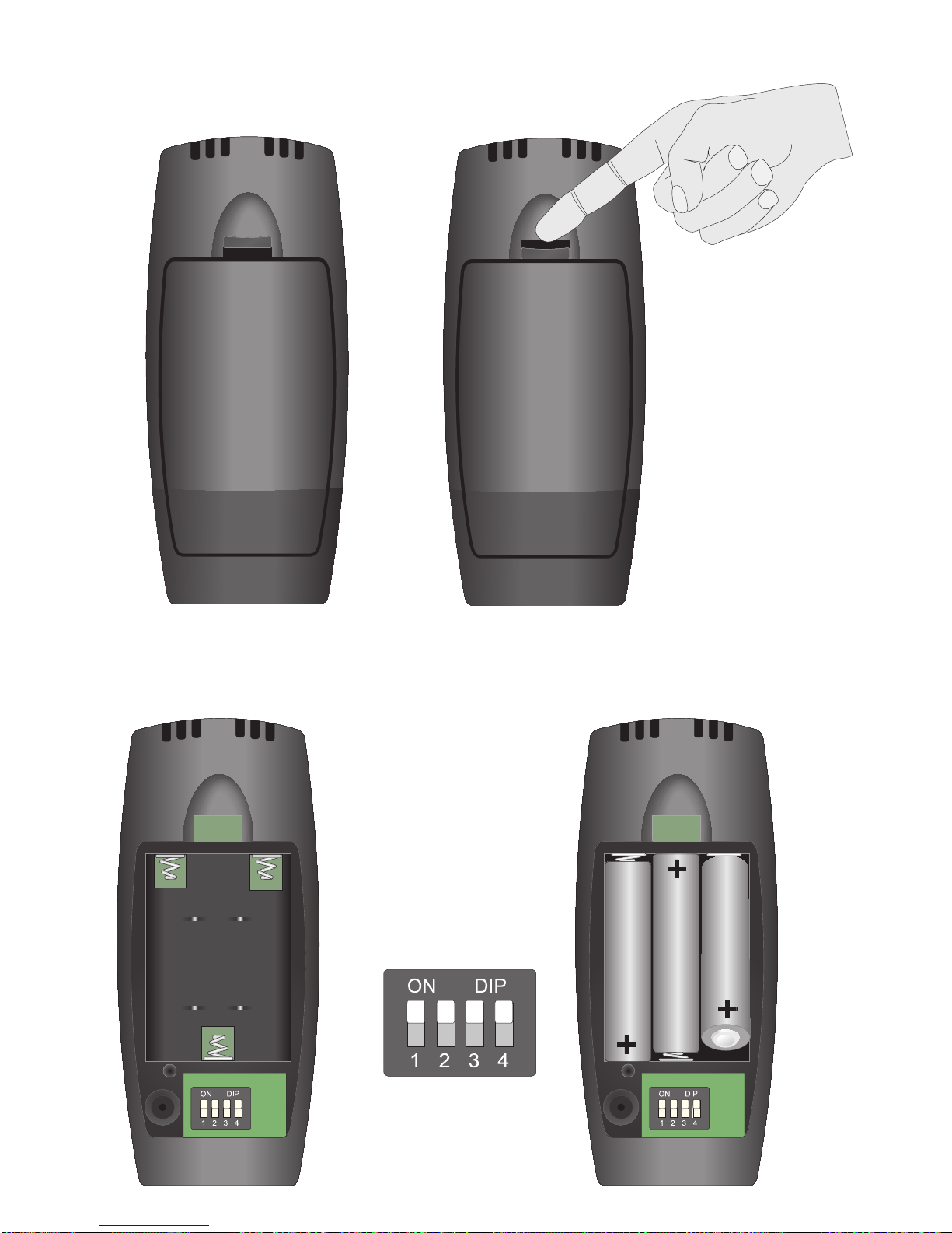
The battery compartment cover is opened by pulling the retaining catch towards the cover and then away from
the body of the handset.
+
+
Positive end inserted
last when fitting
Positive end removed
first when replacing
The batteries, three “AAA-RO3 Size 3, 1.5v” are fitted with the positive end, marked with a ” ” symbol, at the
opposite end to the spring. Always fit the batteries by inserting the negative end, marked with a “ “symbol,
against the spring first. When removing the batteries the positive end should be lifted out first.
Ensure that all the dip
switches are set to the ON
position when fitting the
batteries for the first time.
+-

© EUROHEAT DISTRIBUTORS (H.B.S) LTD. April 2008 Operating Instructions Part number IN1174 Ed. B
7
Ensure that the batteries are fitted the correct way round as the
receiver will not work if incorrectly fitted.
Pull down the two latching levers gently and pull
them away from the receiver, allowing the cover to
pivot downwards and be released.
The batteries supplied with the kit are for test purposes only and will only have a limited life, new batteries
should be fitted as soon as is practical.
Ensure that all the dip
switches are set to the ON
position when fitting the
batteries for the first time.

© EUROHEAT DISTRIBUTORS (H.B.S) LTD. April 2008 Operating Instructions Part number IN1174 Ed. B
8
Clip on the manual override switch
cover plate.
Receiver Plugs
Insert the plug that connects the receiver’s output to the motor with the retaining latch uppermost.
The latch will be heard to click when the plug is fully engaged.
If it becomes neccessary to remove the motor plug the latch should be
squeezed to release the locking mechanism.

© EUROHEAT DISTRIBUTORS (H.B.S) LTD. April 2008 Operating Instructions Part number IN1174 Ed. B
9
Testing the Receiver’s Motor Operation
Moving the switch on the receiver to its ON position will cause the motor to run
for ten seconds. If the motor is installed in the stove it will drive the stove to its
maximum firing position.
Moving the switch on the receiver to its OFF position will cause the motor to run
for ten seconds. If the motor is installed in the stove it will drive the stove to its
minimum firing position.
Receiver Indicator Light
Moving the switch on the receiver to its RS position will set the receiver to respond to radio signals from the
handset.
The red indicator will flash slowly and continuously when
the batteries are almost exhausted.
The red indicator will flicker when receiving a signal from
the handset.
WARNING
Low battery power in the transmitter or receiver can affect the operation of the remote control in any mode. In
some cases the motor which operates the air flaps may run continuously with low battery conditions. Replace
batteries to stop this occurring.

© EUROHEAT DISTRIBUTORS (H.B.S) LTD. April 2008 Operating Instructions Part number IN1174 Ed. B
10
Setting the Display to Show Temperature
in Fahrenheit or Centigrade.
The handset will automatically show temperature in fahrenheit unless the
handset is re-programmed to change the display to read centigrade.
To change the display to read temperature in degrees centigrade remove the
back battery access panel and identify the “reset” switch which is to the left of
the “dip switches”.
By carefully inserting, briefly, a fine point, for which the end of an unravelled
paper clip is ideal, the display will show every symbol in its memory for two
seconds and then change to show just the “F” symbol.
Pressing the “ ” button will change this to a
“C” symbol. The handset is now programmed
to display temperature in degrees centigrade
and after a few seconds the display will
show its normal temperature and function
display.
Repeating the above procedure will reset the
handset to read fahrenheit.
TEMPERATURE CONVERSION CHART
ºC ºF ºC ºF ºC ºF ºC ºF
0 32.0 10 50.0 20 68.0 30 86.0
1 33.8 11 51.8 21 69.8 31 87.8
2 35.6 12 53.6 22 71.6 32 89.6
3 37.4 13 55.4 23 73.4 33 91.4
4 39.2 14 57.2 24 75.2 34 93.2
5 41.0 15 59.0 25 77.0 35 95.0
6 42.8 16 60.8 26 78.8 36 96.8
7 44.6 17 62.6 27 80.6 37 98.6
8 46.4 18 64.4 28 82.4 38 100.4
9 48.2 19 66.2 29 84.2 39 102.2
+
Tabla de contenidos
Otros manuales de Mando a distancia de Euroheat