ETC Installation Guide
Echo Preset Station
3. Terminate EchoConnect wires. EchoConnect is topology free; you may
install the wires in any combination of bus, star, loop, or home-run.
a. Strip 11mm (7/16in) from the ends of each power pigtail wire
provided in the termination kit and from the installed control wires.
b. Use the WAGO connectors provided to connect the power pigtail
wires and the installed Belden 8471 control wires. One WAGO should
be used for the white wire pair (data +) and one for the black wire pair
(data -). Open the terminal levers on the WAGO connector and insert
the installed Belden 8471 wire and the lead from the power pigtail
into the terminals then close the levers.
c. Install the two pin connector from the power pigtail to the mating
receptacle on the station electronics.
Install the Station in the Back box
Note:
For some flush mount applications with certain trim rings it
may be necessary to remove the station’s back cover for insertion into
the back box.
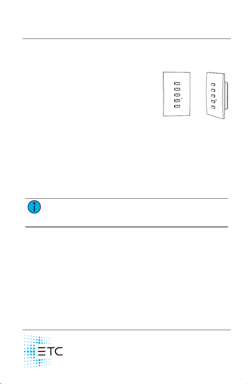
1. Insert the station electronics and
wiring into the back box. The
arrow on the mounting plate must
be directed up.
2. Use receptacle spacers as needed
to provide a flush mounted
station.
a. Fold a spacer in a zig-zag
fashion and press them
together to achieve the
required thickness to fill the
gap between the station, wall surface, and the back box.
b. Cut off and discard the excess.
c. Place the stack between the station electronics and the flush mounted
back box.
3. Secure the station with two screws. If using spacers, insert the screws
through the spacers as well.
Note:
Over tightening of the mounting screws may result in poor
button activation.
4. Install the button caps (included with the faceplate kit) so that the clear
light tunnels protrude through the caps.
Echo Preset Station Page 5 of 8 ETC