
ERMCO AHT-1 Guía

1
CIRCUIT BREAKER OPERATION & ADJUSTMENT (AHT‐1 & T‐12)
Preliminary factory adjustment of the breakers is expected to give
signal light contact connuity under the following four condions:
1. When the cocking lever is moved beyond the open posion.
2. When the cocking lever is moved beyond the closed posion.
3. When the trip bar is moved, but before the breaker contacts are
tripped.
4. When the breaker has tripped completely.
To achieve these condions, the posion of the two signal light
contacts and the calibrang screw are factory preset. To obtain light
indicaon from the reset posion, the cocking lever must be moved
toward the light tower when the contacts are open. To obtain light
indicaon from the closed posion, the cocking lever must be moved
toward the contacts when the contacts are closed. This allows the
light switch operaon to be checked outside the tank.
Following this preliminary adjustment, the breakers are calibrated
and packaged.
To obtain the same condions when the breaker is installed in a
transformer requires the correct amount of free travel at each end of
the operang handle moon.
Obtaining the correct free travel is oen a cut‐and‐try procedure due
to variaon in the handle locaon, breaker locaon and tank
dimensions. To facilitate this adjustment the following steps may
prove useful.
1. Bolt breaker to support, ghten screws firmly and back offthe
screw under the trip bar ½ turn.
2. Install the operang handle assembly in the tank and ghten
the clamping nut unl the gasket stop booms out. Further
ghtening is undesirable.
3. Posion the operang handle to align the yellow arrow with the
“R” on the bearing, allowing about ¼” clearance between the
handle stop and the bearing stop. Posion breaker in the
cocked posion with the contacts open.
4. Screw the connecng rod (link arm) in to the cocking lever unl
the holes in the rod and operang arm mate. Insert a coer pin
in the holes, hold coer pin in place and move the operang
handle to check for the following operaons:
a. Close and open the breaker.
b. Close breaker, trip light contact manually (avoid tripping
main breaker contacts). Reset light by moving operang
handles to the “L” posion.
c. Trip breaker contacts and try reseng the breaker. A
properly adjusted breaker will have approximately ¼” of
travel lebetween the handle and bearing stops. If
breaker fails to operate properly, adjust connecng rod
unl the above operang condions are obtained.
FOR MORE INFORMATION VISIT ermco‐eci.com
ERMCO COMPONENTS, INC | 1607 Industrial Road | Greeneville, TN 37745
5. Install coer pin permanently; avoid binding between rod and
lever.
6. Install signal light in tank wall; ghten clamping nut only enough
to compress the gasket. Avoid over‐ghtening.
7. Posion calibraon control mechanism (overload lever) on the
breaker at the “normal” posion. Insert the preformed end
control wire into the breaker overload lever and thread the
control cable (sheath) into the support on the breaker and lock
the connecon by pinching the support around the cable
sheath.
8. Posion the calibraon control mechanism (overload lever) on
the breaker in the “normal” posion. Hold the control assembly
lever on the operang handle bearing in the “normal” posion.
Thread the control cable through the hole in the cable support
and lock the connecon by pinching the support around the
cable sheath. Twist the control wire into and around the
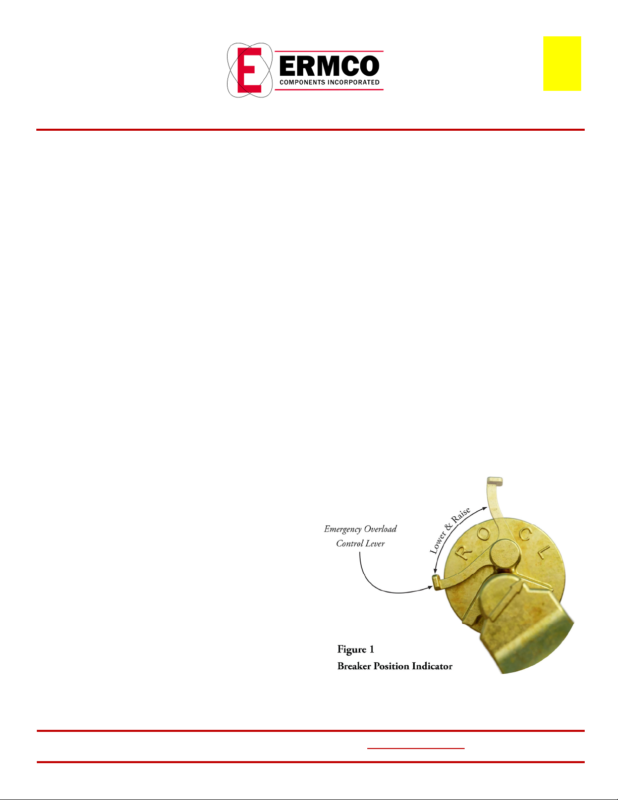
emergency overload control lever as show below.
9. Connect signal light winding to terminal on the breaker.
10. Connect signal light winding to the signal light.
11. For breakers without emergency overload and signal light, the
following procedure is recommended to make the breaker
assembly adjustment in the transformer tank:
a. Place breaker in the cocked posion with the contacts
open.
b. Adjust threaded connecng rod (link arm) so that the
yellow arrow on the operang handle is aligned with the
“O” on the bearing.
c. Check breaker for proper reset and close operaons.
Adjust connecng rod (link arm) to achieve proper
operaon, if required.
ECI
A1‐15
11/04
A1‐16
10‐21
2
STANDARD OPERATING INSTRUCTION GUIDE FOR LOW‐VOLTATE BREAKER & SIGNAL LIGHT
WARNING : ON SINGLE PHASE & THREE PHASE TRANSFORMERS
WITH THE SECONDARY CIRCUIT BREAKER OPEN, THERE MAY BE
SUFFICIENT COUPLING TO THE WINDING SO THAT PERCEPTIBLE
SHOCK MIGHT BE OBTAINED FROM THE SECONDARY TERMINALS.
A circuit breaker when provided is mounted inside the tank, under
the liquid level. The funcon of this breaker is to open the low‐
voltage circuit and protect the transformer from faults or severe
overloads. A red signal light, when provided, gives the warning that
the load has reached a value near the tripping point of the breaker.
The signal light remains lighted unl reset (turned off) by means of
the breaker‐operang handle. Transformers should not be operated
under load condions that will cauase the red light to appear
frequently, since it indicates an overload on the transformers. When
such a condion exists, it is recommended that a larger transformer
be substuted to avoid impairing the life of the smaller unit.
The circuit breaker operang handle and posion indicator are
shown in Figure 1. Transformers are shipped with the circuit
breakers closed. To open the low voltage circuit manually, move the
handle so that the pointer moves from “C” (closed) to “O” (open), at
which point the circuit is open. Verify that the circuit breaker is
latched in the “open” posion.
To insure that the discharge of the stac charge, which is somemes
present in the low voltage winding due to capacitance, it is
recommended that the low voltage be grounded aer opening the
circuit breaker unl the high voltage is disconnected.
To close the breaker aer manual opening move the handle so the
arrow points towards “C”. If the breaker has been tripped it is
necessary to move the arrow towards “R” to reset the breaker
before closing the breaker by moving the arrow towards “C”.
If a fault exists or and excessive load exists at the me the breaker is
closed, the breaker will reopen even though the operang handle is
held in the “C” (closed) posion.
To reset the signal light, rotate the handle to the “L” (light), and then
return to “C” (close). If the light fails to go out, the transformer is sll
over heated.
Provision is made for checking the signal light bulb when the
transformers is in service, to do this, rotate the handle to “L” (light)
FOR MORE INFORMATION VISIT ermco‐eci.com
ERMCO COMPONENTS, INC | 1607 Industrial Road | Greeneville, TN 37745
and the light should come on. If it does not, the bulb should be
replaced. The bulb is a standard six‐volt, GE bulb No. 44, and is
replaceable from outside the transformer and by removing the signal
light lens. Aer checking return the operaon handle to “C”. Faulty
bulbs should be replaced, since operang the transformer with the
faulty bulb or without a bulb may result in radio noise.
Some circuit breakers are equipped with emergency overload
devices, which can be used to restore service following a circuit
breaker operaon due to overload. With the emergency lever in the
normal posion the breaker will trip at its normal sengs as
calibrated at the factory. Moving the lever in clockwise direcon (see
Figure 1) increases the seng so that a higher temperature is
required to trip the breaker. This emergency seng provides extra
load capacity and sll permits manual breaker operaon, and also
retains short circuit protecon of the transformer. It is important
that the emergency seng be used only when and as long as
absolutely necessary, because its use will result in a reducon of
transformer life.
A meter seal is provided on the emergency lever to prevent
tampering. It is recommended that a new seal be applied when it is
returned to the normal posion aer emergency operaon.
ECI
7‐7D
A1‐17
3/02
3
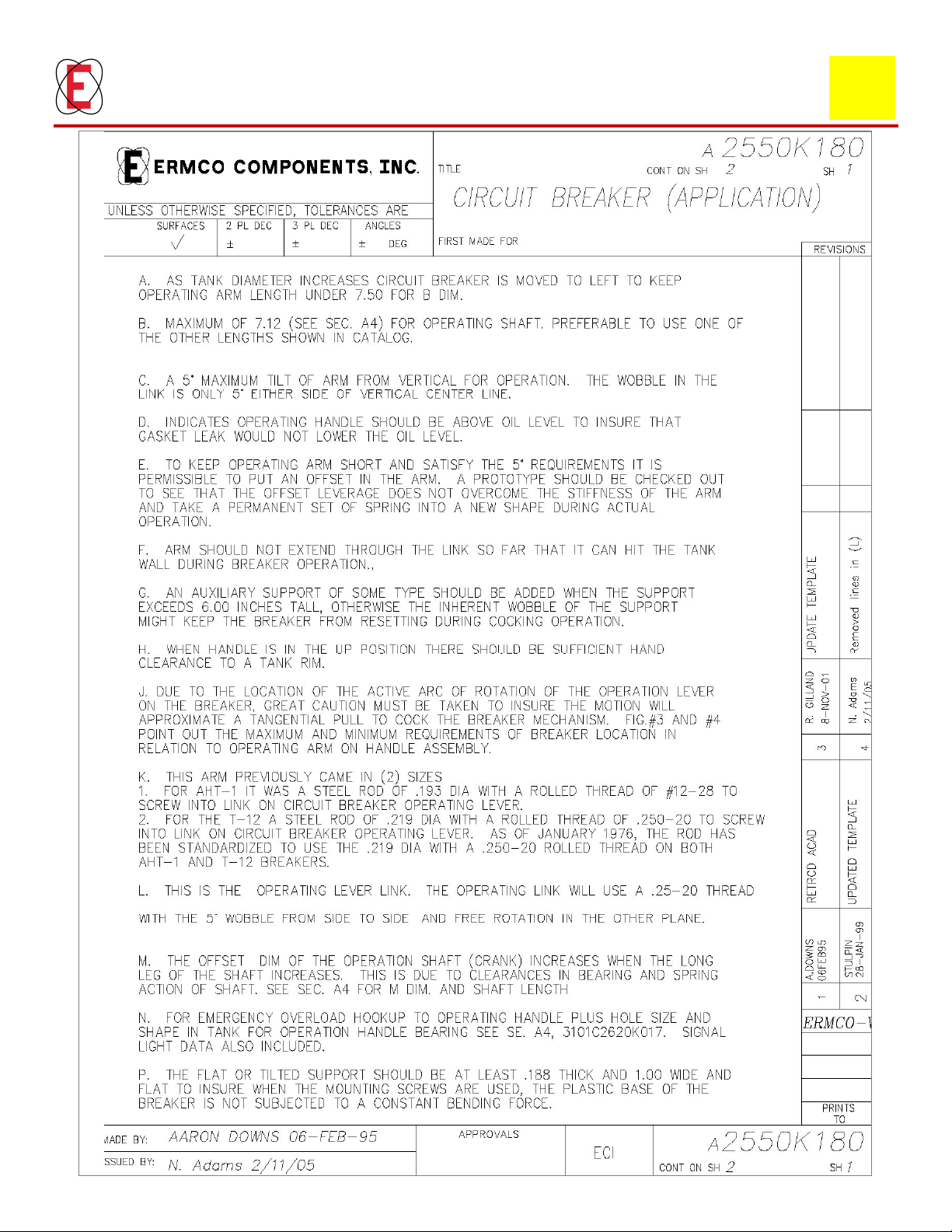
CIRCUIT BREAKER APPLICATION
ECI
7‐7D
A1‐12
02/05
4
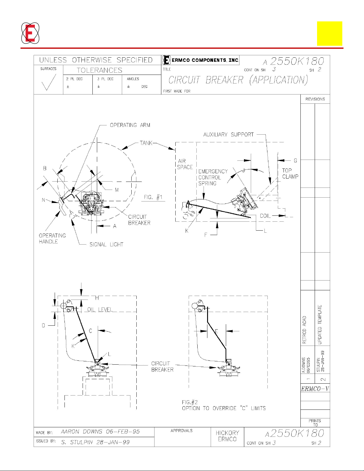
CIRCUIT BREAKER APPLICATION
ECI
7‐7D
A1‐13
01/99
5
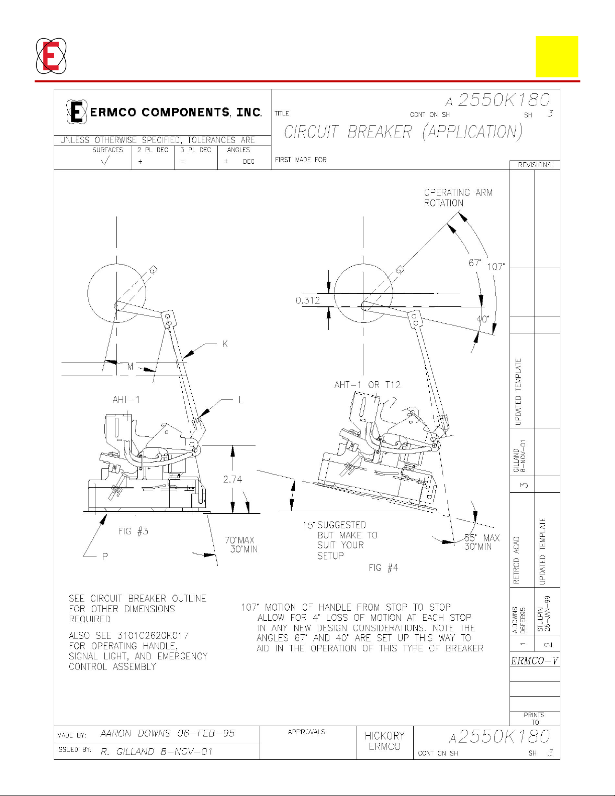
CIRCUIT BREAKER APPLICATION
ECI
7‐7D
A1‐14
11/01
Este manual sirve para los siguientes modelos
1


