ENERVEX Multiple Fireplace Guía del usuario

3940011 12.12 System Installation & Operating Manual
USA
CAN
Multiple Fireplace
Exhaust System
ENERVEX Inc.
1685 Bluegrass Lakes Pkwy.
Alpharetta, GA 30004
P: 770.587.3238
F: 770.587.4731
T: 800.255.2923
www.enervex.com
Job Name:
Installer:
Installation Date:
SYSTEM & COMPONENT DESCRIPTION
DIMENSIONS & CAPACITIES
SYSTEM INSTALLATION & SET UP GUIDELINES
ELECTRICAL CONNECTIONS & INSTALLATIONS
START-UP AND CONFIGURATION
SEQUENCE OF OPERATION
TROUBLESHOOTING
......................................... Chapter 1
............................................................ Chapter 2
............................. Chapter 3
............................. Chapter 4
................................................... Chapter 5
............................................................. Chapter 6
........................................................................ Chapter 7
READ AND SAVE THESE INSTRUCTIONS!
CM
I
N
T
E
R
T
E
K
L
I
S
T
E
D
CU
S

2
3940011 12.12
1. SYSTEM & COMPONENT DESCRIPTION
1.1 General ...............................................................................................3
1.2 Component Description.......................................................................3
1.3 System Description .............................................................................4
2. DIMENSIONS & CAPACITIES
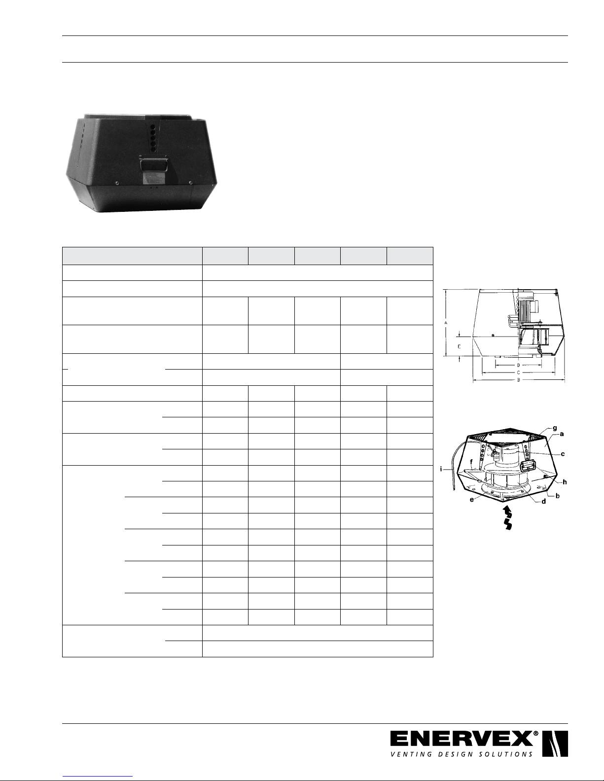
2.1 EBC 30 ................................................................................................5
2.2 RSV .....................................................................................................6
2.3 XTP2 Sensor........................................................................................7
2.4 Stack Probe..........................................................................................7
2.5 ADF/ADM.............................................................................................8
2.6 ISOKERN IBV Fireplace......................................................................9
3. SYSTEM INSTALLATION & SET-UP GUIDELINES
3.1 General .............................................................................................10
3.2 Exhaust Fan Installation.................................................................... 11
3.3 Control, XTP2 and Stack Probe Installation ......................................12
3.4 ADM Installation.................................................................................13
4. ELECTRICAL CONNECTIONS & INSTALLATIONS
4.1 General ..............................................................................................14
4.2 Wiring the Safety Circuit.....................................................................15
4.3 XTP2 Connections .............................................................................16
4.4 Wiring the Draft System.....................................................................17
5. START-UP AND CONFIGURATION
5.1 Control Settings..................................................................................20
5.2 Choosing the Draft Set-Point .............................................................20
5.3 Checking Fan Rotation (3-phase only)...............................................20
5.4 Setting the Damper Postion ...............................................................21
6. SEQUENCE OF OPERATION
...........................................................................................................22
7. TROUBLESHOOTING
...........................................................................................................23
!
TO REDUCE THE RISK OF FIRE, ELECTRICAL SHOCK OR INJURY TO PERSONS,
OBSERVE THE FOLLOWING:
1. Use this unit in the manner intended by the manufacturer. If you have questions, contact the manufacturer at the address or telephone
number listed on the front of the manual.
2. Before servicing or cleaning the unit, switch off at service panel and lock service panel to prevent power from being switched on accidentally.
3. Installationworkandelectricalwiringmustbedonebyaqualiedperson(s)inaccordancewithapplicablecodesandstandards.
4. Follow the appliance manufacturer’s guidelines and safety standards such as those published by the National Fire Protection Association
(NFPA), and the American Society for Heating, Refrigeration and Air Conditioning Engineers (ASHRAE), and the local code authorities.
5. This unit must be grounded.
!
Caution: Indicates an imminent hazardous situation
which, if not avoided, may result in personal injury or
property damage.
Danger: Indicates an imminent hazardous
situation which, if not avoided, will result in
death, serious injury or substantial property
damage.
Symbol Legend:
The following terms are used throughout this manual to bring attention to the presence of potential hazards or to important information
concerning the product.

3
3940011 12.12
1. SYSTEM & COMPONENT DESCRIPTION
1.1 General
TheENERVEXMultipleFireplaceExhaustSystemisamodulatingexhaustsystemdesignedspecically
forthecommonventingandexhaustofmultipleISOKERNgas-redreplacesinresidential,multi-story
buildings. The system includes an EBC 30 Control, one or more RSV fans, an ABB Variable Frequency Drive
(ifapplicable),anADMautomateddamper,anISOKERNIBVmodelreplaceandanISOFLAMESgaslogset.
EachreplaceueconnectstoacommonverticalventthathasaRSVfanattheterminationpoint.TheEBC30
modulates the fan speed to maintain the pre-set, negative pressure in the vent.
1.2 Component Description
a. EBC 30 Constant Pressure Regulator
The EBC 30 Constant Pressure Regulator controls the system to maintain the required pressure
set-point. The control regulates draft pressures by modulating the fan speed based on readings
from a pressure transducer (XTP2).
b. RSV Chimney Fan
Thereplacesystemisventedthroughoneormore RSV model chimney fans. If the fan operates
on 3-phase voltage, a Variable Frequency Drive (VFD) is used to modulate the fan speed. The
VFD connects in between the fan junction box and EBC 30. A single phase fan connects directly to
the add-on triac board inside the EBC 30 control box.
c. XTP2 Sensor
The XTP2 Sensor is an external pressure transducer that monitors pressure in the vertical common
vent. The transducer converts measured pressure into a corresponding voltage. This voltage is
relayed to the control to modulate the damper position and/or fan speed, thus regulating the
pressure at the set point.
d. ADM
The ADM is a motorized damper controled by a two-postition (open/close) actuator. The damper
connects to standard B-vent. If necessary, the stroke length of the actuator easily adjusts to open
less than 90o.
The actuator includes an auxiliary switch that ties into the burner’s thermal limit circuit, which
operates on mili-volts. When the actuator moves to its open position, the auxiliary switch
closes. When the pilot heats up the thermocouple, the limit circuit fully closes and releases the gas
valve.Thecircuitpreventsthereplacefromoperatingwhenthedamperisclosed.Intheeventof
a mechanical or electrical failure, the auxiliary switch reverts to the normally open position
and closes the gas valve.
e. ISOKERN IBV Model Firerplace
AnIsokernmodelIBV36orIBV46replaceisstandardforthereplacesystem.Thereplaces
aremadespecicallyforB-ventconnectionbutcanbeadaptedtototherventmaterials.Each
replaceueincludesanactuator/balancingdampersystemthatinterlockswiththethermallimit
circuitoftheburner,whichcontrolsthegasvalvefeedingthereplace.Eachreplaceisinstalled
with one of three iginition options: push-to start (manual), remote control pilot or electronic ignition.

4
3940011 12.12
Gas
Valve
ON/OFF damper
and actuator with
end-switch
ON/OFF
Contact
ON/OFF
Contact
ON/OFF
Contact
ON/OFF
Contact
ENERVEX
Stack Probe
XTP
Transducer
EBC30 Control
RSV Chimney Fan
ISOKERN fireplace
Multiple ISOKERN Fireplace system
with Single stack and Draft Control
Gas
Valve
ON/OFF damper
and actuator with
end-switch
ISOKERN fireplace
Gas
Valve
ON/OFF damper
and actuator with
end-switch
ISOKERN fireplace
Gas
Valve
ON/OFF damper
and actuator with
end-switch
ISOKERN fireplace
Fig. 1
1.3 System Description
During operation, the EBC 30 maintains a constant negative pressure in the vertical common vent and
replaceconnectors.WhentheADMopenstoitspreset,openpositionandthepilotislit,theburner
receives a signal to release the gas valve. The XTP senses the change in pressure and the EBC30 speeds
upthechimneyfanuntilthedraftset-pointissatised.Thespeedofthefanmodulatesandvaries
dependingonthenumberofreplacesinoperation.Thefanissizedbasedontheamountofdraftneeded
whenallreplacesareburning(worst-casescenario).

5
3940011 12.12
2.1 EBC 30 Control
EBC 30 Control
Power Supply V 1x120VAC
Amperage A 6.3
Operating Temperature °F / °C -4 to 122/-20 to 50
Range of Operation inWC / Pa 0-0.6 / 0-150
Tolerance inWC / Pa 0.01/3+/-10%
Control Signal mA max. 10
Control Relay Max. 120 VAC/8A
Output VAC 10-120
VDC 0-10
Dimensions A in / mm 14.65 / 372
B in / mm 11.03 / 280
C in / mm 4.22 / 107
Weight lbs / kg 8.9 / 4.0
EMC Standard Emission EN 50 081-1
Immunity EN 50 082-2
2. DIMENSIONS & CAPACITIES

6
3940011 12.12
Sound Diagram
1) Not required if using a VFD
2.2 RSV Chimney Fan
a Top Section
b Bottom Section
c Motor
d Centrifugal Impeller
e Inlet for Impeller
f LockingHinge
g Bird Screen
h Carrying Handle
i Wiring Conduit
Model RSV 200 RSV 250 RSV 315 RSV 400 RSV 450
Discharge Vertical
Fan Type Centrigual Impeller
Max. Discharge
Velocity FPM 1,729 2,222 2,771 2,752 4,134
Actual Discharge
Velocity FPM 2.9 x
CFM
1.9 x
CFM
1.2 x
CFM
1.03 x
CFM
1.03 x
CFM
Voltage V AC 1x120 3x208-240/3x400
RPM 1600 1720
Amps A 1.4 2.9 5.8 3.5/2.1 6.5/3.8
Power Ratings kW 0.10 0.16 0.35 0.75 1.5
HP 0.15 0.2 0.5 1 2
Weight lbs 47 60 88 97 128
kg 18 26 35 44 58
Dimensions Ain 11.03 13.20 14.97 16.94 23.23
mm 280 335 380 430 590
B x B in 15.37 19.11 22.85 25.61 25.61
mm 390 485 580 650 650
C x C in 12.22 15.17 18.32 20.69 20.69
mm 310 385 465 525 525
Ø D in 7.88 9.85 12.41 15.76 15.76
mm 200 250 315 400 400
Ein 3.15 3.94 4.53 5.12 8.54
mm 80 100 115 130 217
Temperature Rating Interm. 575°F / 300°C
Cont. 482°F / 250°C

7
3940011 12.12
XTP2 Sensor
Power Supply VDC 12-36
Amperage mA <20
Output VDC 0-10
Operating Temperature °F/°C 0 to 160 / -18 to 71
Accuracy inWC/Pa +/- 0.08%
Dimensions D in/mm 3.70 / 94
E in/mm 5.12 / 130
F in/mm 6.18 / 157
G in/mm 3.13 / 80
Weight lbs/kg .6/.3
2.3 XTP Sensor
2.4 Stack Probe
Stack Probe
Dimensions H in / mm 4.25 / 108
I in / mm 3.50 / 89

8
3940011 12.12
2.5 ADM
Model ADM 6 ADM 8 ADM 10 ADM 12 ADM 14 ADM 16 ADM 18 ADM 20
Dimensions Ø A in 68 10 12 14 16 18 20
mm 152 203 254 305 356 406 457 508
Ø B in 5.88 7.88 9.88 11.788 13.88 15.88 17.88 19.88
mm 146 197 248 298 349 400 451 502
Model ADM 22 ADM 24 ADM 26 ADM 28 ADM 30 ADM 32 ADM 34 ADM 36
Dimensions Ø A in 22 24 26 28 30 32 34 36
mm 559 610 660 711 762 813 864 914
Ø B in 21.88 23.88 25.88 27.88 29.88 31.88 33.88 35.88
mm 552 603 654 705 756 806 857 908

9
3940011 12.12
2.6 ISOKERN IBV Fireplace
Model IBV 36 IBV46
BTU Natural Gas 70,000 77,000
LiquidPropane 65,000 69,000
Max. Inlet Supply Pressure NG in WC / Pa 7 / 1750
Max.InletSupplyPressureLP in WC / Pa 13 / 3250
Dimensions A in / mm 43.0 / 1092 53.0 / 1346
B in / mm 25.25 / 641 25.25 / 641
C in / mm 70.5 / 1791 70.5 / 1791
D in / mm 31.75 / 806 31.75 / 806
E in / mm 37.0 / 940 47.25 / 1200
F in / mm 27.13 / 689 37.5 / 953
G in / mm 22.5 / 572 33.5 / 851
H in / mm 10.25 / 260 9.88 / 251
I in / mm 20.25 / 514 20.25 / 514
J in / mm 5.0 / 127 5.0 / 127
Weight lbs / kg 1500 / 680 1700 / 771

10
3940011 12.12
3.1 General
The code requirements for a mechanical draft system are different than those for a gravity venting system
used with gas applications. Generally, the mechanical draft system must be installed a minimum of 3 feet
away from any forced air inlet located within 10 feet and a minimum of 4 feet away from any door
or window. For complete information, consult ENERVEX or your local building codes.
Installation must be in accordance with these instructions and all local codes, or in their
absence, the National Fuel Gas Code, NFPA 54/ANSI 223.1.
This installation manual is for the ENERVEX venting system and assumes that the ISOKERN replaces
have already been installed. Installion of the ISOKERN replaces, the gas logs and the pilot assembly
should be performed by a qualied ISOKERN technician or a certied gas service agent or supplier. If you
have any questions regarding installation of these components, consult the ISOKERN installation manual.
ImportantinformationaboutISOKERNIBVreplaces
• ISOKERNIBVmodelreplacesaredesignedforusewithstandardB-vent.ENERVEXdoesnotrecommend
installing more than 100’ of B-vent in the vertical run of the system. If the common vertical vent is over
100’, you must use a listed pressure stack or another alternative. For information on circumstances where it is
appropriate to use B-vent in a vertical common vent greater than 100’, contact ENERVEX.
• Iftemperaturesinthereboxexceed160°F,theISOKERNIBVreplacehasathermallimitswitchthat
opens the safety circuit and closes the gas valve.
DO NOT mount the transducer inside an airtight enclosure. It uses the room pressure
as reference pressure.
!Adequate intake air must be provided for combustion of the replaces; otherwise,
improper operation and inadequate venting of deadly ue gases may result.
3. SYSTEM INSTALLATION & SET UP GUIDELINES
Tabla de contenidos


