enertexbayern Enertex KNX TP Secure Coupler Guía rápida


1171-EnertexKNXSecureCoupler_US-3.odt, 2020-10-02 Seite 2 von 14
Note
The content of this document may not be reproduced, distributed, distributed or stored in any form
whatsoever, in whole or in part, without the prior written consent of Enertex® Bayern GmbH.
Enertex® is a registered trademark of Enertex® Bayern GmbH. Other product and company names
mentioned in this manual may be trademarks or trade names of their respective owners.
This manual is subject to change without notice or announcement and does not claim to be complete or
correct.
Contents
Security Notes.............................................................................................................................................. 3
Commissioning............................................................................................................................................ 3
Boot ......................................................................................................................................................... 3
Display...................................................................................................................................................... 3
Reset........................................................................................................................................................ 4
Functional overview.....................................................................................................................................
ETS Parameter.............................................................................................................................................. 5
Terms....................................................................................................................................................... 5
Version requirements............................................................................................................................... 5
Topology................................................................................................................................................... 5
Device properties..................................................................................................................................... 7
Device specific parameters...................................................................................................................... 7
General.....................................................................................................................................................................7
Special functions......................................................................................................................................................8
Behaviour of main line ......................................................................................................................................8
Behaviour of sub line ........................................................................................................................................8
Routing...............................................................................................................................................................
Filter..........................................................................................................................................................................
Physical address filter........................................................................................................................................
Group address filter ........................................................................................................................................11
Standard....................................................................................................................................................11
Extended group address filter...................................................................................................................12
Filter blocking (bypass)..........................................................................................................................................13
Latest data .................................................................................................................................................1
Technical data............................................................................................................................................1
Enertex® Bayern GmbH – Ebermannstädter Straße 8 - 1301 Forchheim - Deutschland - mail@enertex.de

1171-EnertexKNXSecureCoupler_US-3.odt, 2020-10-02 Seite 3 von 14
Security Notes
•Installation and assembly of electrical equipment may only be carried out by qualified
electricians.
•When connecting KNX / EIB interfaces, KNX™ training is required.
•Failure to observe this instruction may result in damage to the unit, fire or other hazards.
•This guide is part of the product and must remain with the end user.
•The manufacturer is not liable for costs or damages caused to the user or third parties
by the use of this device, misuse or interference of the connection, malfunctions of the
device or other connected devices.
•The opening of the housing, other unauthorized modifications and / or conversions to
the device will void the guarantee!
•The manufacturer shall not be liable for any inappropriate use.
Commissioning
To operate the Enertex® KNX IP Secure Coupler, you need:
•Two KNX/EIB lines
Boot
When the unit is powered up, the display shows the product name.
The boot time is approximately 3 seconds. During this time, the green/red/yellow LED will start
running for a short time. At the end of the booting process the display shows "KNX Ready",
The device is supplied with power via the bus line connected to the MAIN terminal.
The green LED flashes every second with a pulse duty cycle of 1:30.
Display
After one minute the display turns off automatically. To turn it on again, press the DISPLAY but-
ton on the front panel briefly.
When the display is turned on, pressing the DISPLAY key initiates a scrolling through various in-
formation pages.
Page 1
Routing information such as group addresses, filter information and device addresses of the
senders.
Main => Sub * : *
Activity of routing from main to subline. The * - character is animated and rotates with in-
coming telegrams on the respective page
Sub => Main * : *
Activity of routing from sub to main line. The * - character is animated and rotates with
incoming telegrams on the respective page
PHY: xx.yy.zzz
Device address of the indicated telegram
GA: aa/b/ccc
Enertex® Bayern GmbH – Ebermannstädter Straße 8 - 1301 Forchheim - Deutschland - mail@enertex.de

1171-EnertexKNXSecureCoupler_US-3.odt, 2020-10-02 Seite 4 von 14
group address of the indicated telegram
Note: t higher telegram load only a part of the group addresses is visible (approx. 3 displays
per second).
Page 2 shows the firmware version, physical address, serial number, bus voltage and status of
sub and main line
Seite 3 shows information on telegram load
Seite shows the FDSK as long as the device is not set to the secure mode.
Pressing the DISPLAY button for more than 5 seconds will block (=bypass) all filters of the rou-
ting. During this phase, the display will show a countdown until it automatically returns to normal
mode with activated filters. This function of the DISPLAY key can be blocked via the ETS appli-
cation (see section Filter blocking (bypass)).
At the front side there are three LEDs. The green LED is blinking every second with a 1:30 duty
cycle and indicates operational readiness. The red LED indicates programming mode, the yellow
LED shows bus activity.
Reset
If the device is to be reset to the factory settings, the PROG key on the front panel must be pres -
sed for 10 seconds. After this time the red LED starts blinking - then the PROG button can be re-
leased and the unit will perform the reset to factory settings.
Functional overview
The device has the following functionalities:
•KNX Secure Coupler
◦Connection for KNX TP subline (SUB)
◦Connector for KNX TP Main Inie (MAIN)
◦KNX TP Routing for coupling of KNX lines or areas (SUB and MAIN)
◦Use as line repeater
◦Telegram forwarding and filtering by physical address
◦Telegram forwarding and filtering by group address with up to 62 filter blocks
◦Programming the application via secure communication ("data secure")
•Displays
◦LEDs for operational readiness, TP communication and programming mode
◦OLED display for status messages, parameter messages, etc.
•Special functions
◦Measurement of TP bus voltage for sub and main line (OLED display)
◦Measurement of current consumption for sub and main line (OLED display)
◦248 bytes TP APDU packet length of the KNX bus
◦Configuration of a programming lock for the SUB or MAIN line or both in plain or secure
mode
◦Configuration of the DISPLAY button to switch on blocking (bypassing) the activated routing
filters.
•Performance
◦Specification of a maximum TP data rate for writing KNX telegrams for each line
Enertex® Bayern GmbH – Ebermannstädter Straße 8 - 1301 Forchheim - Deutschland - mail@enertex.de

1171-EnertexKNXSecureCoupler_US-3.odt, 2020-10-02 Seite 5 von 14
◦Buffering up to 1024 telegrams each for SUB and MAIN
ETS Parameter
Terms
Encryption, encrypted If devices send data information via the TP bus or IP network, they are
generally readable by third parties. These only require access to the TP bus or IP network for
reading. Encryption of the data in this context means that the contents of the telegrams are no
longer to be interpreted if the encryption parameters (for example passwords) are unknown.
Key, Key Parameter A series of numbers known only to the ETS project. These numbers are
used to transform the data in both directions: encryption and decryption.
FDSK (Factory Default Setup Key) The initial factory key. This key is used when commissio-
ning the initial programming. A new key is loaded into the device, whereby this process is en-
crypted with the FDSK. The FDSK key is then no longer valid. It is reactivated only when reset -
ting the device to factory settings.
Secure Mode If the device is parameterized via the ETS so that the communication is only en-
crypted, this is referred to as secure mode.
Plain Mode If the device is parameterized via the ETS so that the communication is only unen-
crypted, this is called unsecured mode.
Version requirements
For accurate operation of the devices in secure mode, ETS 5.7.4 or higher is required.
Topology
To insert the coupler into an ETS project as area coupler, this project must have a TP backbo-
ne. The coupler must be assigned to the address XX.0.0 (see www.knx.org), where XX repres-
ents the desired area.
To insert the coupler into an ETS project as line coupler, the main line must be of type TP. The
coupler must be assigned to the address XX.YY.0 (see www.knx.org), where XX represents the
desired area, YY the desired main line
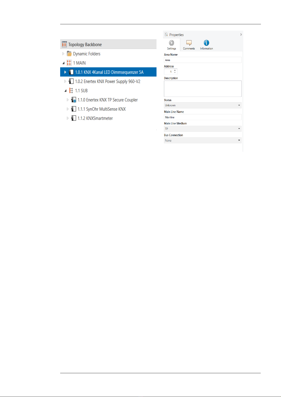
Example with the following topology stored in the ETS:
Enertex® Bayern GmbH – Ebermannstädter Straße 8 - 1301 Forchheim - Deutschland - mail@enertex.de
1171-EnertexKNXSecureCoupler_US-3.odt, 2020-10-02 Seite 6 von 14
Figure 1: Topology (left) and properties of the main line
Linien:
•1: MAIN: main line medium TP
•1.1: SUB: sub line medium TP
If the device is used as a line repeater, all filters for group addresses (see below) and physical
addresses must be set to forwarding.
Enertex® Bayern GmbH – Ebermannstädter Straße 8 - 1301 Forchheim - Deutschland - mail@enertex.de

1171-EnertexKNXSecureCoupler_US-3.odt, 2020-10-02 Seite 7 von 14
Device properties
Figure 2: Device properties
Name Any name can be assigned, max. 30 characters
Secure commissioning If enabled, the encryption for commissioning is active: All parameters
are encrypted during transmission.
Device specific parameters
General
Figure 3: General settings of the device
The application parameters and filter tables of the Enertex® KNX TP Secure Couplers can be
downloaded from both the main line and the sub line. It is also possible to limit the parameter
download to the main line or the sub line or both lines. In the latter case, the device can no lon -
ger be accessed until it is reset to the factory default settings by a factory reset.
Example
TP outside line is connected to SUB, the main line to M IN. The coupler is programmed so
that only group addresses according to the filter are routed. For example, it prevents the ad-
dress of the door opener on the M IN line from being accessed by the SUB line. potential at-
tacker would be easily possible to reprogram the filter tables of the coupler. This can be preven-
ted by activating the programming lock
Name Selection options Description
Enertex® Bayern GmbH – Ebermannstädter Straße 8 - 1301 Forchheim - Deutschland - mail@enertex.de

1171-EnertexKNXSecureCoupler_US-3.odt, 2020-10-02 Seite 8 von 14
(Explanation) The device can be programmed
from both the sub and the main line
in the factory default state. This can
be restricted by means of the opti-
ons shown here.
From sub line off/on See parameter dialog
From main line off/on See parameter dialog
Enable special functions off/on Enertex® devices offer special func-
tions to ensure maximum flexibility
for the user
Special functions
Behaviour of main line
Figure 4: Behaviour of main line
Name Selection options Description
ACK for every telegram off/on The coupler acknowledges each te-
legram, even if it does not forward
this telegram
ACK for routed telegram only off/on The coupler only confirms the tele-
grams that it forwards
Repeat routed telegrams if not
ACKed
off/on The coupler repeats unconfirmed in-
dividually addressed telegrams
Max. number of telegrams to
main line
5 .. 50 See parameter dialog
Behaviour of sub line
Enertex® Bayern GmbH – Ebermannstädter Straße 8 - 1301 Forchheim - Deutschland - mail@enertex.de

1171-EnertexKNXSecureCoupler_US-3.odt, 2020-10-02 Seite von 14
Figure 5: Behaviour of sub line
Name Selection options Description
ACK for every telegram off/on The coupler acknowledges each te-
legram, even if it does not forward
this telegram
ACK for routed telegram only off/on The coupler only confirms the tele-
grams that it forwards
Repeat routed telegrams if not
ACKed
off/on The coupler repeats unconfirmed in-
dividually addressed telegrams
Max. number of telegrams to
sub line
5 .. 50 See parameter dialog
Routing
bbildung 6: Routing
Name Selection options Description
Check topology off/on See parameter dialog
Filter
Physical address filter
The Enertex KNX TP Secure coupler can be configured in such a way that physically addressed
telegrams are forwarded, blocked or filtered. Physically addressed means that devices are loa-
ded or programmed across the coupler with the ETS application parameters. If this communicati-
on is blocked, for example, an actuator on the main line cannot be programmed from the sub
line.
If, additionally, broadcast telegrams are also blocked, it is not possible to assign the physical ad-
dress via the coupler using the programming button of the other device, even if the physically
addressed telegrams are forwarded by the coupler.
This applies to all communication that is related to the device address in the specified direction.
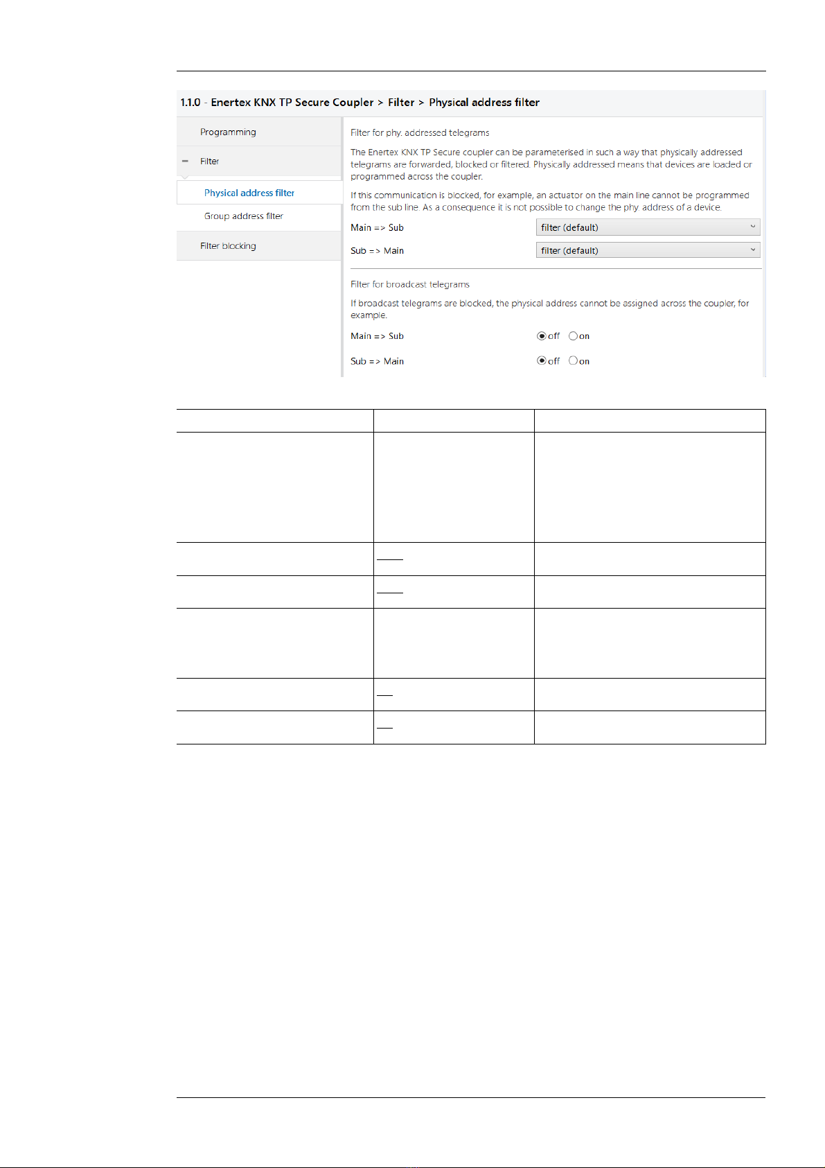
The required parameters are located in the phyiscal address filter (see Figure 7).
Enertex® Bayern GmbH – Ebermannstädter Straße 8 - 1301 Forchheim - Deutschland - mail@enertex.de
1171-EnertexKNXSecureCoupler_US-3.odt, 2020-10-02 Seite 10 von 14
Figure 7: Filter for physically addressed telegrams
Name Selection options Description
Physical address filter The physically addressed telegrams
(e.g. programming of actuators) can
be forwarded, blocked or filtered via
routing. This applies to all communi-
cation that refers to the device ad-
dress in the specified direction.
Main => Sub filter, block, route Direction: MAIN to SUB
Sub => Main filter, block, route Direction: SUB to MAIN
Blocking of broadcast tele-
grams
Broadcast telegrams (e.g. search for
actuators in programming state) can
be forwarded or blocked via the rou-
ter.
Main => Sub off/on Direction: MAIN to SUB
Sub => Main off/on Direction: SUB to MAIN
Enertex® Bayern GmbH – Ebermannstädter Straße 8 - 1301 Forchheim - Deutschland - mail@enertex.de
Tabla de contenidos
Manuales populares de Equipo de iluminación de otras marcas


Qazqa
Qazqa Suplux SL 3 Black 103062 Manual de usuario

Commercial Electric
Commercial Electric 54568141 Manual de usuario

CREE LIGHTING
CREE LIGHTING 304 Series Manual de usuario

Goobay
Goobay 49867 Manual de usuario

ECOMAN ITALIA
ECOMAN ITALIA LED T8 Manual de usuario

Alkalite
Alkalite Krypton KT-81 Manual de usuario


