Important safety instructions ______________________________________________________________ 3
Product __________________________________________________________________________________ 4
Models___________________________________________________________________________________ 5
Technical specifications___________________________________________________________________ 6
Installation
Physical installation ____________________________________________________________________ 7
Electrical installation___________________________________________________________________10
Smart-Home or Smart-Pro Module
Initial conguration ____________________________________________________________________11
Extended features_____________________________________________________________________12
Operation sequence
Immedate charging mode ______________________________________________________________16
Controlled access charging mode _______________________________________________________ 16
Output current adjustement ______________________________________________________________18
Maintenance and cleaning
Maintenance _________________________________________________________________________21
Cleaning _____________________________________________________________________________21
Moving and storage______________________________________________________________________ 21
Troubleshooting
Common problems ____________________________________________________________ 22
Diagnostic code_______________________________________________________________ 23
Contact us ______________________________________________________________________________ 25
Limited Warranty ________________________________________________________________________26
Figure list
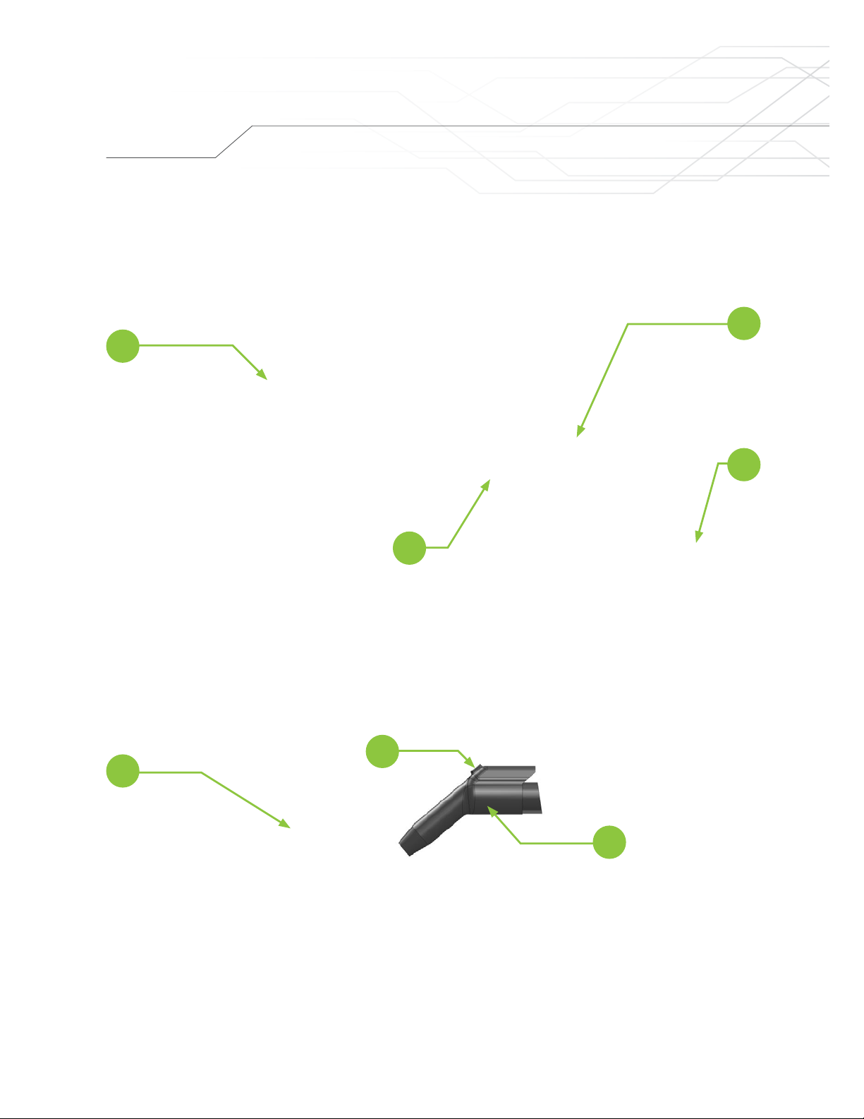
Figure 1: Portable model, Permanent Installation model, Output connector _______________________ 4
Figure 2: Wall mount installation ______________________________________________________ 7
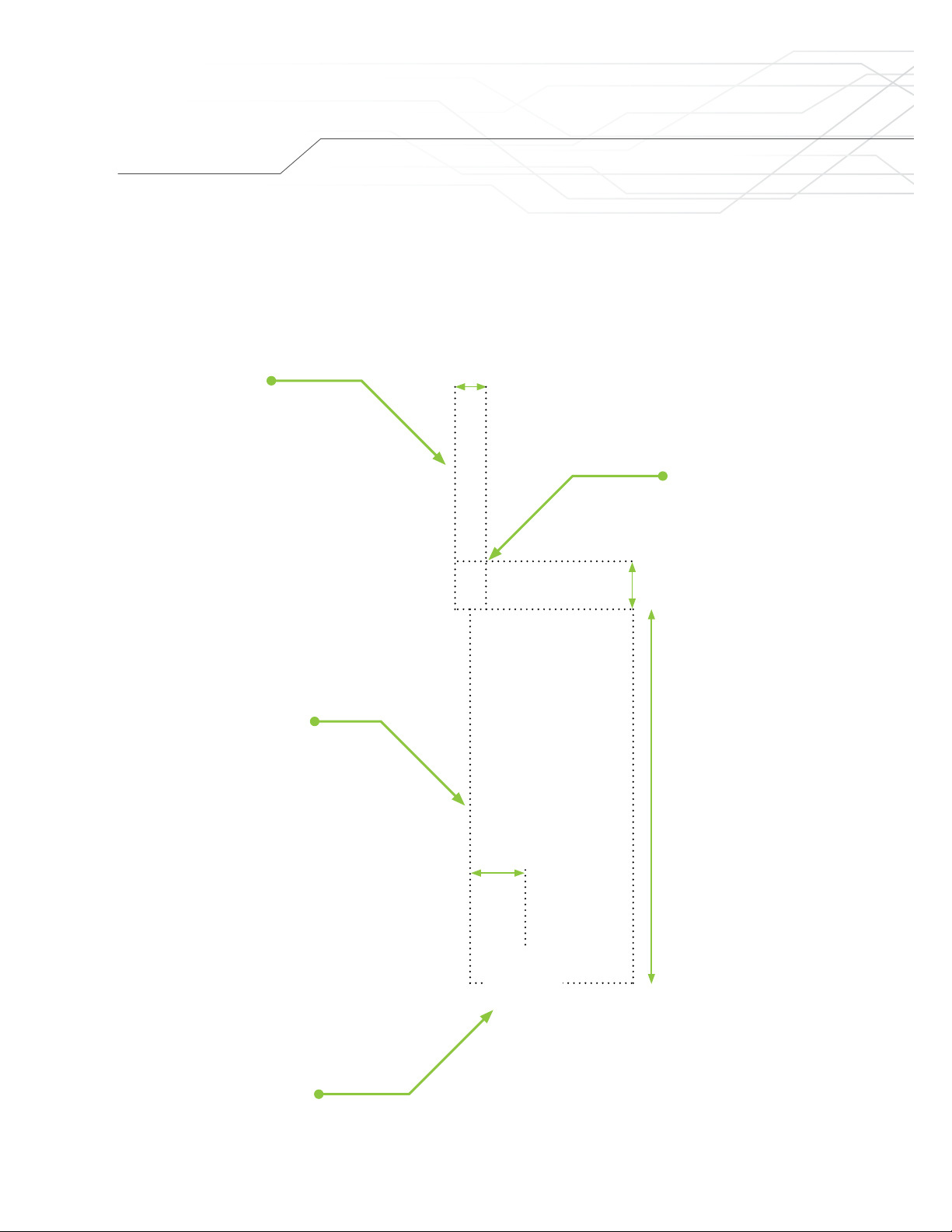
Figure 3: Position of the unit vs the input power receptacle ___________________________________ 8
Figure 4: Installation of padlock for anti-theft protection _____________________________________ 9
Figure 5: Position of DIPSwitch (SW1, R4.10) ____________________________________________ 19
Figure 6: Position of DIPSwitch (SW5, R5.4+) ____________________________________________ 20
Table list
Table 1: Connections inside junction box for permanent installation model_______________________ 10
Table 2: Charging station state based on Main LED color ___________________________________ 17
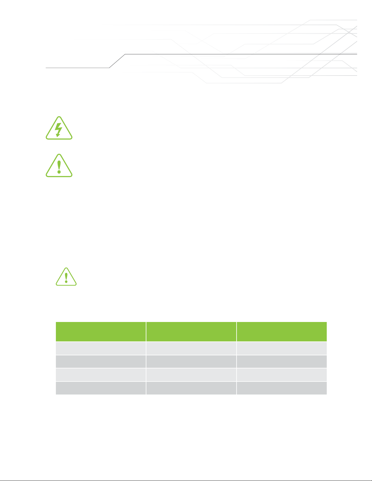
Table 3: Maximum output current vs circuit breaker value ___________________________________ 18
Table 4: Maximum output current adjustment (SW1, R4.10)__________________________________ 19
Table 5: Maximum output current adjustment (SW5, R5.4+)__________________________________ 20
Table 6: Troubleshooting ___________________________________________________________ 22
Table 7: Diagnostic codes __________________________________________________________ 24
Table of contents