Elkay EFC22-A Manual de usuario

ELKAY Undermount Filter EFC22-A/EFU23-A/EFU23D-A
Please read all instructions, specifications, and precautions before installing and using
your water filter system.
Page 1 1000003973 (Rev. A - 05/17)
PARTS LIST
A) Filter Manifold
B) Stage 1, Polypropylene Filter Cartridge P/N: EFU23-PP-A
C) Stage 2, Carbon Block Filter Cartridge P/N: EFU23-MS-A
D) Stage 3, Ultrafiltration Filter Cartridge P/N: EFU23-UF-A
E) Tee Ball Valve
F) 1/4” Tubing (5m)
G) Mounting Screws (2)
H) Mounting Anchors (2)
I) Tee Fitting
J) Connector Clips (5)
K) AAA Batteries (3) - Model EFU23D-A ONLY
L) Installation Manual
EFC22-A
PP MS
TOOLS REQUIRED
• Screwdriver
• Adjustable Wrench
• Utility Knife
• Drill and 6mm Drill Bit
• Tape Measure
• Sefety Glasses
• Towels
• Pencil
• Pan or Bucket
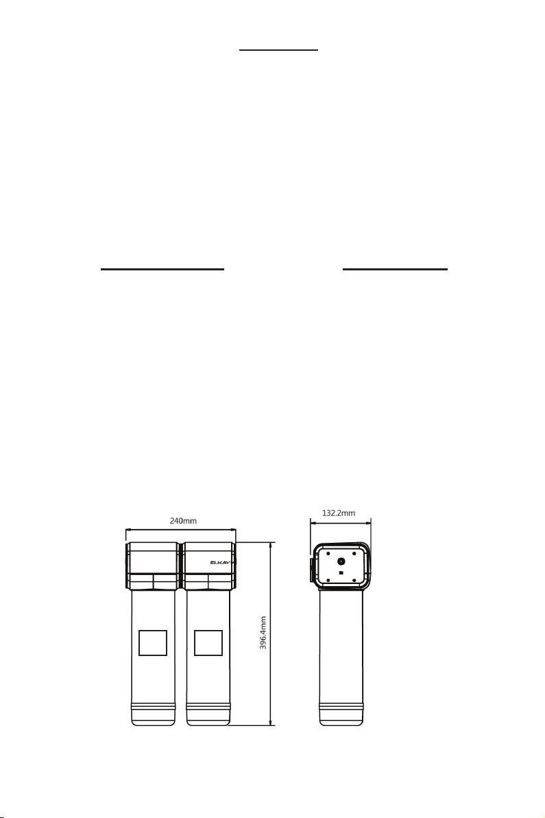
SPECIFICATION
• Rated Operating Pressure: 0.2-
0.6Mpa
• Rated Service Flow: 1.5L/min
• Rated Operating Temperature:
5-38°C
Page 2
1000003973 (Rev. A - 05/17)

Notice
Do not use with water that is microbiologically unsafe or of unknown quality.
Filter housing must be protected against freezing temperatures, frost, snow, sleet, and ice.
Exposure to these elements can produce cracks and product failures.
This product has a limited service life. Because of the product’s limited service life and to pre-
vent costly repairs or possible water damage, we strongly recommend that the head of the filter
be replaced every ten years.
Turn off water supply to head and remove cartridges if it must be left unattended for an extend-
ed period of time.
• For cold water use only. Do not use on hot water line.
• After prolonged periods of non-use (such as during a vacation) it is recommended that the
system be flushed thoroughly. Let water run for 5–6 minutes before using.
• The fi lters recommended for use with this system carry a limited service life. Changes in taste,
odor, color, and/or flow of the water being filtered indicate that the cartridge should be replaced.
• Make certain that installation complies with all state and local laws and regulations.
• Designed for residential use only.
Caution
EFU23-A
EFU23D-A
MS UFPP
MS UFPP
Caution
Caution
Page 3 1000003973 (Rev. A - 05/17)

1. Turn off cold water shut-off valve then turn on the kitchen faucet to cold and allow all water
to drain from line.
2. Disconnect the cold water line from the cold water shut-off valve.
NOTE: If rigid plumbing pipe (metal or plastic) is used, you may need to shorten the pipe using a
hacksaw or pipe cutter to commodate the tee ball valve.
3. Install the tee ball valve onto the supply valve and the cold water line to the top of the tee
ball valve.
NOTE: Do not over tighten the connections. Damage and/or leaks can occur if the connections
are over tightened.
Installation
1. Cold Water
Shut-Off
Valve
2. Cold Water
Line
3. Tee Ball
Valve
Page 4
1000003973 (Rev. A - 05/17)
4. Remove the packaging from the fi lter cartridges. Install the cartridges into the fi lter manifold
by lining up the ports and rotating clockwise to lock them in.
NOTE: Remove black rubber plugs from filter ports before installing.
NOTE: Stage 1 (PP fi lter cartridge) is the left side of the manifold near the manifold inlet.
MS PPUF
EFU23-A Shown
Bottom View
of Filter Manifold
5. Locate a position under the sink to mount the filter system.
NOTE: The system requires a 75mm space at the bottom for fi lter cartridge replacement.
NOTE: Horizontal mounting of the filter manifold is required.
NOTE:Allow space on the right and left side for the tubing to connecting without becoming pinched.
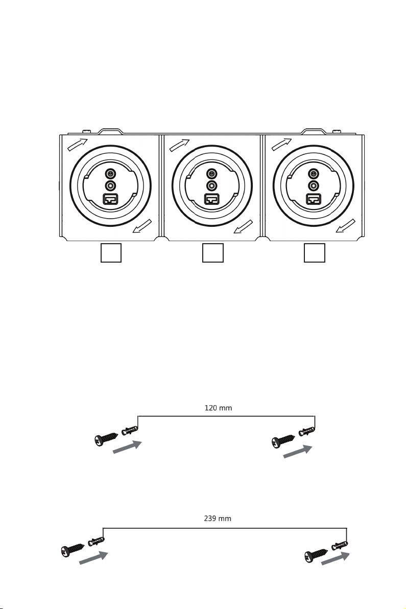
6. Measure and mark the locations for the drill holes. The minimum distance from the cabinet floor
to the center of the holes is 50mm. The horizontal distance between hole centers is 120mm
for EFC22 system and 239mm for EFU23/EFU23D systems.
7. Drill the holes using the 6mm drill bit and drill. Install the anchors and screws.
NOTE: Allow 3mm between the screw head and anchor for the fi lter manifold bracket to hang.
EFC22-A
EFU23-A, EFU23D-A
Page 5 1000003973 (Rev. A - 05/17)

8. Use the ¼” tubing to connect the tee ball valve to the fi lter manifold inlet (IN). Use the utility
knife to cut the tube to length and check for full engagement on quick connect fittings.
NOTE: A straight cut provides the best seal and prevents leaks.
NOTE: Wetting the end of the tube lowers the insertion force.
9. Use the ¼” tubing to connect the dispensing faucet to manifold outlet (OUT).
10. Open the dispensing faucet then turn on the cold shut-off valve and open the tee ball valve.
Inspect for leaks at the filter system and all fi ttings.
11. Flush the system by allowing the water to run to drain for 10 minutes. It is normal for the water
will be cloudy with carbon and air during the fl ush time. After fl ushing the system is ready to
use.
EFU23-A Shown
MS UFPP
IN OUT
Page 6
1000003973 (Rev. A - 05/17)

1. Remove the center manifold cover to access to back of the electronic display.
NOTE: The cover snaps may need to be pushed in with a screw driver at the back of the manifold
Battery Installation (EFU23D-A ONLY)
2. Locate the battery box on the back of the display and remove the label securing the cover.
Slide the cover open in the direction of the arrow.
3. Install the batteries and reinstall the cover.
NOTE:If the display does not activate and beep, confirm that the power switch is in the ON position.
Cover Snaps
1. Manifold Cover
Page 7 1000003973 (Rev. A - 05/17)

1. After the batteries are installed, the electronic display screen will be on for 25s. During this
period:
• Without any button operation, the screen will enter sleep mode after 25s and the display will
turn off.
• With button operation, the time to enter sleep mode will be postponed 25s. Without any button
pressed for 25s, the screen will enter sleep mode.
2. When the electronic display is in sleep mode:
• Press any button and the display will turn on. Without any buttons pressed for 25s, the screen
will enter sleep mode again.
• When a fl ow signal is detected, the screen will turn on. Without any button pressed for 25s,
the screen will enter sleep mode again.
(If 25s is not due and flow signal turns off, the screen will enter sleep mode)
3. Function of reset and set buttons:
• Enter setup: Normally, the display screen will be off. Press any button, and the display screen
will turn on. Press and hold the “Set” button for 3s to enter the setup state. The fi rst-stage
fi lter icon will fl ash.
• Pressing the “Set” button will change to the next fi lter stage. If it is on the third stage, pressing
the button will exit the setup state.
• If you press and hold the “Reset” button for over 3s, the service life of the selected fi lter is reset
to fi ve bars (100%). After resetting the fi lter life, the setup automatically changes to the next
fi lter stage. If it is on the third stage, pressing the button will exit the setup state.
NOTE:When the system is in the setup state for 10s without a button pressed, it will exit and return
to the normal display state.
4. Buzzer function:
• After installing the batteries, the buzzer will sound once.
• Each time the button is pressed, the buzzer sounds once.
• When the fi lter is in use and the if the fi lter surplus life ≤1 scale (<5%), the buzzer sounds once
every 6s to remind the user to replace the filter.
Electronics Operation (EFU23D-A ONLY)
Page 8
1000003973 (Rev. A - 05/17)

1. Filter Life:
• 5 bars mean: 75%≤ remaining life≤100%;
• 4 bars mean: 50%≤ remaining life<75%;
• 3 bars mean: 25%≤ remaining life<50%;
• 2 bars mean: 5%≤ remaining life<25%
• 1 bar means: 0< remaining life<5%; the filter icon fl ashes.
• Replacement due: the fi lter bar will be empty and fl ashing.
2. Producing Water:
When the filter is not being used, the display will stay off.
When the filter is being used, the display will stay on for
25s and the producing water icon will be fl ashing. After 25s,
the display turns off.
Display (EFU23D-A ONLY)
3. Water Cutoff:
When the remaining life hits 0% and replacement is due, the solenoid valve is closed. This
closes the water outlet and the water cutoff icon will be on.
At the same time, the corresponding filter will fl ash and show empty.
4. Filter Early Warning:
If the remaining life of any level of filter has ≤1 bar, the fi lter’s early warning icon will fl ash.
5. Flushing Prompt:
Conditions for flushing startup: when the fi lter is not used for 3 days or after reset of the fi lter
life. The flushing icon will display and fl ash during the next
use to warn the user to flush the fi lter. It can be used after fl ushing for 10min.
6. Battery Capacity
1. Filter Life
6. Battery
2. Producing Water
4. Filter Early
Warning
3. Water Cutoff
5. Flushing Prompt
Page 9 1000003973 (Rev. A - 05/17)

Filter Cartridge Replacement
1. Turn off the water at the tee ball valve and open the faucet to relieve pressure in the filter system.
2. Unlock the filter cartridges by turning counter-clockwise.
3. Line up the ports, insert the cartridge, and turn clockwise to lock.
4. Reset the filter life.
5. Flush the system by allowing the water to run to drain for 10 minutes. It is normal for the water
to be cloudy with carbon and air during the flush time. After flushing the system is ready to use.
Name of filter component Recommended throughput Recommended replacement interval
PP fi lter cartridge 3-5t 3 months
MS filter cartridge 2-3t 6 months
UF filter cartridge 2-4t 24 months
Troubleshooting
LEAKS BETWEEN THE CARTRIDGE AND THE MANIFOLD:
1. Turn off the water at the tee ball valve and open the faucet to relieve pressure in the filter system.
2. Unlock the filter cartridges by turning counter-clockwise.
3. Line up the ports, insert the cartridge, and turn clockwise to lock.
4. Turn on the tee ball valve, close the faucet and inspect for leaks.
LEAKS AROUND THE FITTINGS:
1. Turn off the water at the tee ball valve and open the faucet to relieve pressure in the filter system.
2. While pulling the 1/4˝ plastic tubing with one hand, press in on the collar around the inlet and/
or outlet fi tting. Check to make sure that the plastic tubing is cut squarely and that it is not
scratched or crimped.
NOTE: If the plastic tubing is unevenly cut or scratched, cut off 10-20mm and re-install the tubing.
3. Turn on the tee ball valve, close the faucet and inspect for leaks.
LEAKS AT THE TEE BALL VALVE:
1. Turn off cold water shut-off valve. Turn on the kitchen faucet to cold and dispensing faucet.
Allow all pressure to drain from line.
2. Locate the tee ball valve.
• If the plastic tubing is leaking, follow the previous steps (“Leaks around the fittings”).
• If the thread between the water supply adapter and the cold water line is leaking tighten more
securely.
3. Turn on the cold water shut off valve and close the faucets. Inspect for leaks.
THE ELECTRONIC DISPLAY IS NOT ON:
1. Remove the center manifold cover to access to back of the electronic display.
NOTE: The cover snaps may need to be pushed in with a screw driver at the back of the manifold.
2. Locate the flow meter wires and confirm that it is plugged into the display.
If you continue to have issues or if your issue is not listed here, please contact customer support.
Warranty
The Undermount Filter EFC22-A/EFU23-A/EFU23D-A is warranted to be free from defects in
materials and workmanship for a period of one year from date of installation.
Warranty is limited to repair or replacement of defective component.
Page 10
1000003973 (Rev. A - 05/17)
International Customer Care 630-575-4755 IntlCare@elkay.com
Este manual sirve para los siguientes modelos
2
Tabla de contenidos
Idiomas:
Otros manuales de Sistema de filtración de agua de Elkay


