Elinchrom Digital 2400 RX Manual de usuario
Elinchrom S.A Digital RX 01.02.2011 ENG (73256) Printed in Switzerland
USER MANUAL
GEBRAUCHSANLEITUNG
MANUEL D’UTILISATION
Digital 1200 RX
Digital 2400 RX
230V – 10256
110V – 10255
230V – 10258
110V – 10257
EN
DE
FR

2
P.S: Technical data subject to change.
The listed values are guide values which may vary due to tolerances in components used.
Introduction 3
Declaration of conformity, disposal and recycling, CE marking 4
Safety notice and precaution 4
Before you start 5
Control Panel 6
Functions 7, 8
fuses 9
Flashheads 10
Flashheads compatibility 11
Flashheads Technical Data 12
Wireless Remote Control and Flash Triggering
Troubleshooting
13
Guarantee 39
Table of contents

3
EN
The quality of light and exceptional performance is the result of long research, applica-
tion of demanding principles, the long experience of ELINCHROM in lighting products for
the studio and the utilization of the latest technology in this area.
Totally integrated to the range of the ELINCHROM ashes, the Digital RX Flash generator
maintain the traditional look and function that is ELINCHROM.
Digital RX Flash Generator
The Elinchrom Digital RX is manufactured by Elinchrom S.A. CH -1020 Renens/Switzerland
Dear Photographer,
Thank you for buying your Digital RX ash generator.
All Elinchrom products are manufactured using the most advanced technology. Carefully selected
components are used to ensure the highest quality and the equipment is submitted to many
controls both during and after manufacture. We trust that it will give you many years of reliable
service.
All Digital RX ash units are manufactured for the studio and location use of professional
photographers.
Only by observance of the information given, can you secure your warranty, prevent possible
damage and increase the life of this equipment.
Note:
This equipement has been tested and found to comply with the limits for a class B digital device, pursuant to Part 15
of the FCC Rules and meets all requirements of the Canadian Interference-Causing Equipement Regulations. These
limits are designed to provide reasonable protection against harmful interference in a residential installation. This
equipement generates, uses, and can radiate radio frequency energy and, if not installed and used in accordance with
the instruction manual, may cause harmful interference to radio communications. However, there is no guarantee that
interference will not occur in a particular installation. If this equipement does not cause harmful interferences to radio
or television reception, which can be determined by turning the equipement off and on, the user is encouraged to correct
the interferences by one or more of the following measures:
- Reorient or relocate the receiving antenna.
- Increase the separation between the equipement and receiver.
- Connect the equipement into an outlet on a circuit different from that to which the receiver is connected.
- Consult the dealer or an experienced radio/TV technician for help.
Elinchrom S.A. is not responsible for any radio or television interference caused by unauthorised modications of
this equipement or the substitution or attachment of connecting cables and equipement other than those specied by
Elinchrom S.A. The correction of interference caused by such unauthorised modication, substitution or attachment will
be the responsibility of the user.
FCC Class B Compliance Statement
Introduction

4
CE marking
The shipped version of this device complies with the requirements of ECC directives
89/336/ECC «Electromagnetic compatibility» and 73/23/ECC «Low voltage
directive».
Notational Conventions
The meaning of the symbols and fonts used in this manual are as follows:
Pay particular attention to text marked with this symbol.
Failure to observe this warning endangers your life, destroys the device, or
may damage other equipement
Supplementary information, remarks, and tips follow this symbol.
Text which follows this symbol describes activities that must be performed in
the order shown.
«Quotation marks» indicate names of chapters or terms
!
i
Disposal and recycling
This device has been manufactured to the highest possible degree from materials
which can be recycled or disposed of in a manner that is not enviromentally
damaging. The device may be taken back after use to be recycled, provided that
is returned in a condition that is the result of normal use. Any components not
reclaimed will be disposed of in a environmentally acceptable manner.
If you have any question on disposal, please contact your local ofce or your local ELINCHROM
agent (check our website for a list of all ELINCHROM agents world wide).
This device complies with Part 15 of the FCC Rules. Operation is subject to the following two
conditions:
1. This device may not cause harmful interference.
2. This device must accept any interference received, including interference that may cause
undesired operation.
Product name: Professional Studio Flash
Generator
Trade name: ELINCHROM
Model number(s): Digital RX
Name of responsible party: Elinchrom S.A
Av. De Longemalle 11
1020 Renens / Switzerland
Phone : +41 21 637 26 77
Fax: +41 21 637 26 81
We, Elinchrom S.A., hereby declare that the equipement bearing the trade name and model
number specied above was tested conforming to the applicable FCC rules, and that all the
necessary steps have been taken and are in force to assure that the production units of the
same equipement will continue to comply with the Comissions requirements.
Declaration of conformity

5
EN
• Keep ash units out of reach whenever possible.
• Switch off when not in use and disconnect ashheads.
• Do not use in restricted areas (like hospitals, etc.)
• Do not use near ammable/explosive material.
• It must be protected from dripping water and from extremely dusty conditions
• The unit must ALWAYS be plugged into an EARTHED electrical socket.
• This equipment should be used only in a dry environment
• If the unit has been exposed to very cold conditions, sudden exposure to warm or humid air
may cause condensation => the unit should acclimate for some time to prevent condensa-
tion.
• There is high voltage and can be high currents, so please apply all the usual safety precau-
tions when handling the unit, changing fuses, modelling lamps etc.
• Do not open the unit. In the event of damage or apparent failure, contact a repair service or
• Always switch off the unit before connecting or disconnecting ashheads
• Check always if ashhead connections are plugged in and locked correctly
Flash Tubes and Modelling lamps
• Flash tubes and modelling lamps in use are very hot!
• Never touch a ash tube or lamp before the unit cooled down and is disconnected from the
mains.
• Do not re ashes from short distance (less than 1m) directed to a person and avoid looking
into the ashlight!
• Keep generally distance to operating units.
• Always switch off the unit before connecting or disconnecting ashheads!
• The head connector must always be locked correctly before any use.
• Never store liquids or drinks on the power pack panel or closed to the unit!
• Flash systems store electrical energy in capacitors by applying high voltage.
• For your safety, never open or disassemble your ashes.
• Only an authorised service engineer should open or attempt to repair the units.
• Internal defect charge capacitors may explode whilst the unit is in use, neve
switch on a not proper working ash unit.
!
Before you start ! User Safety Information

6
Overview of Controls
1. Mains inlet socket
2. Fuse AC supply (16 AT, slow blow)
3. Illuminated mains switch
4. Modelling control (on/off free or prop)
5. Open ash and charge indicator
6. Slave cell on/off
7. Handle
8. Photocell receptor
9. Acoustic recharging signal (Beep)
10. Synchro-sockets, Amphenol + jack 3.5 mm
11. Charge speed (slow charge 230 V = 10 A)
12. Decrease power adjustment in 1/10
f-stops, with ADF
13. Increase power adjustment in 1/10
f-stops
14. Power display
15. Socket for remote or USB - Multi Link
16. Increase modelling power
17. Decrease modelling power
18. Lamphead (on/off) outlet A
19. Lamphead (on/off) outlet B
20. Socket outlet A (with security catch)
21. Socket outlet B (with security catch)
Control Panel
15
11
21
10
12
9
3
1
14
7 8
2
20
18
4
13
16 17 19
65

7
EN
Operating Instructions
The power control provides simultaneous and continuously variable adjustment
of the modelling lamp and the ash power in step of 1/10 f-stop. The display,
provides digital power information, in f-stop from 3.5 to 8.5 for the "Digital
2400 RX" and 2.5 to 7.5 for the "Digital 1200 RX".
Digital Power Regulation (12 and 13)
The actual ash power is displayed in a f-stop compatible format. The power
range is 6 f-stops. The digital display, provides continuous power indication
of the ash and modelling lamp. The controls cover a continuous output
range from full power 1/1 to 1/32th in 1/10th f-stop steps. During charging or
discharging the display "ashes". In case of overheating or malfunction, the
display shows "ER" for error.
Digital Power Display (14)
On/Off Switch (1)
By pressing this touch button the Digital RX is switched on or off.
This unit is protected by a thermal circuit breaker to avoid overheating. Should this
occur, the unit turns off automatically and cannot be operated! After a break for
cooling, the ash is ready again for operation.
Modelling Lamp Controls (4-16-17)
• Proportional: The modelling lamp will be adjusted automatically in proportion, when
the ash power is set to another value with touch button 12 or 13.
• Free: To set ash- and modelling lamp values individually.
• Modelling Lamp off
Note: There is an additional ON/OFF switch for the modelling lamp at the ashhead!
The ashhead control button A/B must be switched on for the selected ashhead.
Before connecting the digital RX for the rst time, make sure that your mains supply and the
rating set on the equipment (electrical specication plate) are compatible to 110V or 230V.
• Connect lampheads ensuring that lamphead touches (18-19) are Off.
• Connect the mains cord in the inlet socket (1)
• Select charging rate (11) (" " slow position), only when the mains supply is too limited.
• Select modelling lamp setting (4)
• Connect the synchro lead (10)
• Check that the photocell’s switch (6) is in the required position.
• Use the touch buttons (12 - 13) to select the desired power.
• The open ash (5) will light up, indicating that the unit is ready for operation.
Fonctions

8
Charge Ready Beep (9)
Open Flash (5)
Slow Charge (3)
Photocell On/Off (6)
Synchronisation Socket
Flashheads Control button
The green LED indicates that the slow charge function is selected.
This position is recommended if the mains line capacity is limited for the standard
fastcharge mode.
When the green LED is illuminated the ash may be released manually.
The release is blocked during charging, but not when the unit discharges.
The integrated discharge system is protected by a thermic cut out.
In order to restrict the heating of the unit, we suggest to release a ash with the
green touch (5) "READY" after each strong reduction of power (more the 2f-stop).
This allows to release the excess of energy in the ash tube.
You will gain time and extend the life span of your power packs.
The Photocell (8) is activated when the green LED (4) is illuminated. When switched
on, the pack can be remotely triggered by another ash unit! The Digital RX photocell
is specially designed to work under ambiant light situation in your studio, direct light
or other strong lights may reduce the sensitivity of the cell. In difcult situations e.g.
blinding, sunlight or obstacles, the additional cell with 5 m cord (extensions available)
solves most problems.
Press this touch (9) to activate the acoustic signal
Once recycled, an acoustic signal (beep) indicates that the power pack is ready.
These buttons switches on the ashhead sockets.
Standard / Elinchrom Amphenol socket or 3.5 mm mini-jack (10).
N.B. Do not link ELINCHROM power packs via sync cable to other brands.
ELINCHROM uses low voltage (5V) for security reasons. Other systems may have
higher voltages and could cause damages.

9
EN
This unit is protected by security device.
Should the unit not work properly, due to a defective power component,
the security would instantly stop the charge.
The power pack requires a check up at a technical Elinchrom service.
Overvoltage security
Relation of power range between the outlets
Guide aperture is based on the " Digital S or Digital SE " lamphead and the 50° reector,
distance 1 m/3.3 ft and lm ISO 100/21 DIN.
Digital 1200 RX Digital 2400 RX
Scale Ws f-stop Scale Ws f-stop Power
7.5 1200 (128) 8.5 2400 (180) 1/1
6.5 600 (90) 7.5 1200 (128) 1/2
5.5 300 (64) 6.5 600 (90) 1/4
4.5 150 (45) 5.5 300 (64) 1/8
3.5 75 (32) 4.5 150 (45) 1/16
2.5 37.5 (22) 3.5 75 (32) 1/32
Main Supply
While the MAINS SWITCH (3) is switched OFF (not illuminated), rmly push in the plug of the
original ELINCHROM mains cord (1).
Standard type 5 x 20 mm, 16 AT (tempered). Before exchanging a blown fuse, switch off the unit
and remove mains cable. Depress and turn the fuse holder anti-clockwise 1/8th and remove it.
If the new fuse blows immediately upon reconnection return the pack to an ELINCHROM service
centre for a check-up.
(N.B. Check correct value of the fuse: 16 AT).
Fuse
Fuses for ashheads
Use only FAST BLOW FUSES, type 5 x 20 mm corresponding to the label on each ashhead.
Different modelling lamps require corresponding fuses. Slow blow fuses will not protect the
modelling lamp. The fast blow fuse will protect the triac of the modelling lamp circuit, the
lamp and therefore the ash tube.
Modelling
Lamp switch
Fuse
Fuse
W 110V 240V
200 2 AF 2 AF
250 5 AF 2.5 AF
300 5 AF 2.5 AF
650 10 AF 5 AF
Only use recommended fuse
10
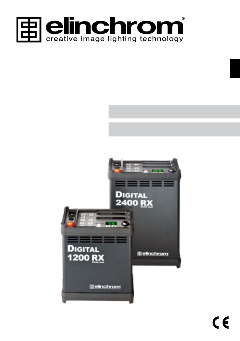
Flashheads
When plugging in a lamphead connector, rst push in the front part, then rmly press in the
whole plug, the rear part being secured by the locking spring.
!Do NOT plug in or unplug lampcords
while the green leds on output A and B
are ON (illuminated)
1
2
Socket
• The ashheads cannot be insulated against humidity and dust.
• Do NOT plug in or unplug lampcords while the green leds on output A and B
are ON (illuminated).
• Never store liquids or drinks on the power pack panel or closed to the unit!
• Do not use near ammable/explosive material (min. 1m distance of any object)
• For your safety, use only Elinchrom ashheads.
• Do not open the unit. In the event of damage or apparent failure, contact a
!
Safety Precautions
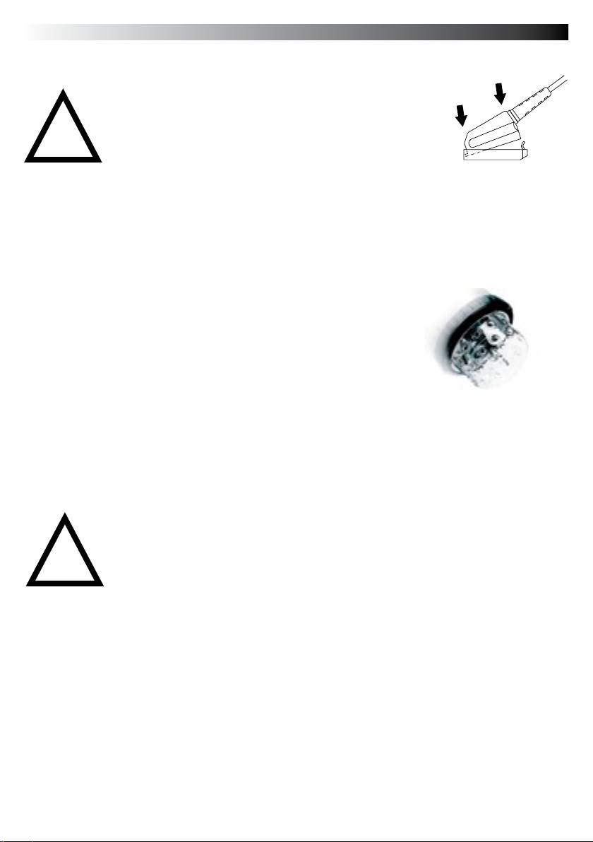
Halogen modelling lamp
Use only the recommended modelling lamp, the Digital S and Digital SE heads
are tted with a 300 W halogen modelling lamp. For 230 V code 23022.
Protective dome
Protective Pyrex Dome
For use with standard halogen lamp GX 6.35 socket.
Transparent, matt or yellow (400° K colour correction), can be tted to all lampheads, except
R heads for which clear or matt security lters are available.
Easy attachment of the protective dome:
• Disconnect the lamphead from the pack
• Loosen the 3 screws of the lamphead reector
• Fit the clips underneath the screw heads and tighten the screws
• Put the dome in place and hook the springs into the airvent holes.
Este manual sirve para los siguientes modelos
1
Tabla de contenidos
Idiomas:


