The UART_SOUT (M.2 Key E pin 22) doubles as a configuration
pin for the clock frequency used by the PAN9028.
Only the 26 MHz configuration is valid since the PAN9028 includes
a crystal with this frequency.
Keep this pin floating or on logical high level during firmware
initialization. A low level during firmware initialization prevents the
firmware from starting up.
H A R D W A R E M O D I F I C AT I O N S
You can modify the PAN9028 M.2 device to suit your application and your specific
host processor by making some hardware modifications.
The following sections describe how you can reconfigure the reference voltages
and how you activate the 3.
SDIO Reference Voltage
In case your host processor board only supports a SDIO signal voltage of 3.3 V
you can reconfigure the PAN9028 M.2 device to use the 3.3 V generated by the
PMIC as VIOSD.
The PAN9028 supports 1-bit or 4-bit SDIO transfer modes with full clock range up
to 208 MHz. The SDIO Interface pins are powered from the VIOSD voltage supply
with either 1.8 V or 3.3 V.
On the PAN9028 M.2 device by default VIOSD is connected to the VOUT1V8 of the
PMIC, hence it is set to 1.8 V.
Clock Configuration Pin
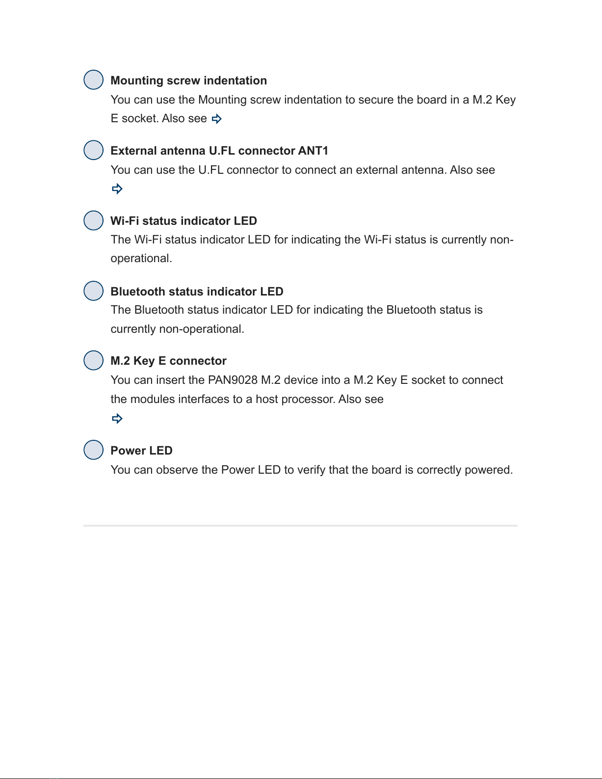
external antenna U.FL connector ANT1