ELECTRODRIVE Tug Tough 10T Manual de usuario

Tug Tough 10T
Operating Manual

Tug Tough 10T Operating Manual—OM0015E-1
This manual contains important safety, installation and operating instructions for this
unit. Read this manual thoroughly and completely, and retain for future reference. This
unit can cause serious injury to personnel or damage to property if used incorrectly,
therefore do not use this machine for any other purpose apart from its intended use.
Using this unit incorrectly may void warranty.
Any damage audible or visible to this unit should be addressed at the time of discovery.
Electrodrive Pty Ltd can provide parts and service support on request through its
service partner company:
Serviced Equipment Pty Ltd
p: 1300 934 471
e: service@fallshaw.com.au
Made in Australia by:
Electrodrive Pty Ltd
2A Ayton Street, Sunshine North VIC Australia 3020
p: 1300 934 471 (within Australia)
p: +61 (03) 9300 8521 (International)
w: www.electrodrive.com.au
© Electrodrive

Tug Tough 10T—Operating Manual
3
Contents
Introduction..................................................................................................................... 5
Features ....................................................................................................................... 5
Operating instructions ................................................................................................... 6
Controls ........................................................................................................................ 6
Driving instructions ........................................................................................................ 8
Safety Check ................................................................................................................ 8
Hitching to a trolley....................................................................................................... 9
Unhitching................................................................................................................... 10
Steering....................................................................................................................... 10
Charging ..................................................................................................................... 10
Maintenance ................................................................................................................. 11
Batteries...................................................................................................................... 11
Tyres............................................................................................................................ 11
Motor and transmission.............................................................................................. 11
Transmission ............................................................................................................... 11
Brakes......................................................................................................................... 11
Motor .......................................................................................................................... 11
Motor controller .......................................................................................................... 11
Throttle lever ............................................................................................................... 12
Fuses .......................................................................................................................... 12
Self-resetting circuit breaker....................................................................................... 12
Warranty ........................................................................................................................ 13
Unauthorised maintenance......................................................................................... 13
Misuse ........................................................................................................................ 13
General wear items not covered under warranty........................................................ 13

4
Appendix 1: Machine rating conditions...................................................................... 14
Appendix 2: Charging procedures for SLA batteries ................................................ 15
Appendix 3: Wiring diagram ........................................................................................ 16
Appendix 4: Spare parts list......................................................................................... 18
Service log .................................................................................................................... 20

Tug Tough 10T—Operating Manual
5
Introduction
The battery powered industrial Tug Tough 10T allows an operator to effortlessly
move heavy wheeled loads and equipment, heavy duty construction, vehicles and
aircraft.
The Tug Tough 10T is a battery powered industrial truck for towing heavy trolleys. It
simply hooks on to your existing trolley with a lock-tow hitch. This converts your heavy
trolley into a powerful, easy to move motorised unit. Productivity is greatly increased,
and back or shoulder strain is eliminated.
This heavy duty model includes the latest developments in DC geared motors with
automatic dynamic braking, as well as a high capacity motor controller.
Features
§Rated to tow up to 10 000 kg
§24 Volt DC power
§Variable speed drive unit
§Electro-magnetic park brake
§Travel speed—up to 2.5 km/h
§Robust steel chassis
§Tiller handle steering that folds up to reduce space when not in use
§Programmable motor controller
§Automatic charger
§Speed governor
§Horn
§Quiet operation, ease of handling and high manoeuvrability
6
Operating instructions
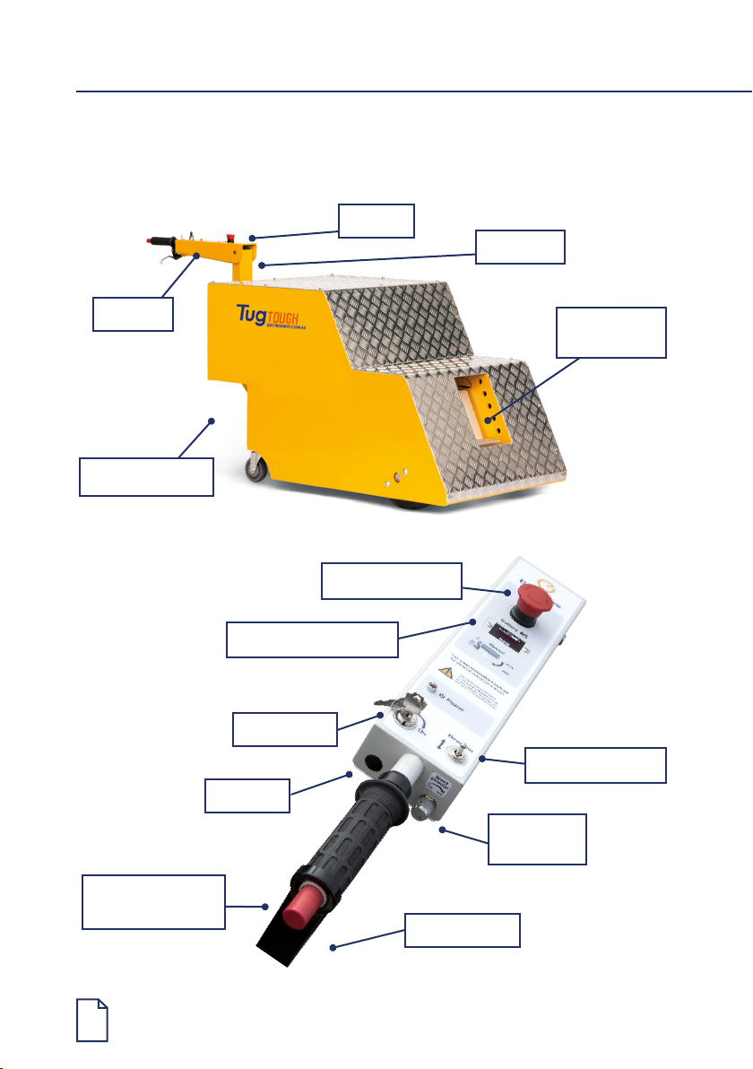
Controls
Lock-tow
hitch
Charger socket
Tiller arm
Tiller post
Key switch
Emergency stop
Emergency
back-off button
Direction selector
Speed
governor
Battery level indicator
Controls
Throttle lever
Horn

Tug Tough 10T—Operating Manual
7
Key switch
The key switch must be turned clockwise to switch the unit on. When ON, the LED
status indicator will be illuminated and the strobe light will ash. It is important to note
that the unit should be switched off and the key removed, whenever it is not in use. This
eliminates the risk of unauthorised movement and also prevents an unnecessary use of
battery power.
Emergency buttons
The controls have two emergency buttons.
1. Emergency stop button
In an emergency, push this button to stop the unit. To release, slightly twist the
button and it will pop back up.
2. Emergency back-off button
When pressed, the Tug will momentarily travel backwards to avoid pinning the
operator against an obstacle, and then stop if the throttle lever is not released. If
this button is pressed when the throttle is released, the Tug will immediately stop. To
reset the back-off function, toggle the direction selector.
Only use the emergency buttons in an emergency.
Battery level indicator
The battery level indicator indicates the amount of charge left in the batteries. When it
appears to be running low, return the unit to the closest charging station to charge the
batteries. Being aware of the level of charge of the batteries will eliminate the possibility
of running low on power whilst away from the charging station.
Direction selector
Toggle the switch to select the desired direction of travel (forward/reverse).
Speed governor
The speed governor limits the speed of travel. It can be adjusted from minimum (slow
walk) to maximum (brisk walk). It is recommended that you set the speed governor to
minimum when learning to operate this Tug, or when towing loads in conned spaces.
Throttle lever
This lever provides variable speed control from zero up to 100% of the governed speed.
Releasing the lever will cause the Tug to decelerate and stop within three seconds.
Charger socket
The plug on the charger is tted into the charger socket mounted on the body panel of
the Tug, next to the tiller post.

8
Brakes
When the throttle lever is released, the unit is slowed electrically by dynamic braking
until the machine and load comes to a complete stop.
Horn
The small yellow button on the console is a horn button. Push to sound the horn,
release to turn off.
Capacity
Refer to the serial plate for the unit’s safe working load, located on the body adjacent to
the tiller post.
Driving instructions
Safety Check
Before using the Tug the operator should complete the following check:
1. The battery charger is not connected.
2. The direction selector works.
3. The emergency stop button is released.
4. The battery isolator key is in the closed position (if tted).
5. The speed governing dial is set at ‘low’, or where desired by the operator.
6. The brakes operate correctly when the throttle lever is released.
7. The battery indicator shows adequate charge.
8. There is no visible damage to the unit.
9. Back-off button works correctly.
Tug Tough 10T—Operating Manual
9
Hitching to a trolley
This Tug has a variety of hitches. In all cases, ensure that the trolley it is being attached
to has its brakes engaged (or chocked), and is free from obstruction. Inspect the trolley
and ensure that the trolley castors are in good condition.
In all cases, ensure that the trolley being attached to has its brakes engaged (or
chocked) and is free from obstruction. Inspect the trolley and ensure that the trolley
castors are in good condition.
Towing a trolley with castors in poor condition can overload the Tug,
and cause damage not covered under warranty.
This Tug is not designed for use on inclined surfaces and doing so may
pose a risk of accident or injury. Use this Tug on level ground only.
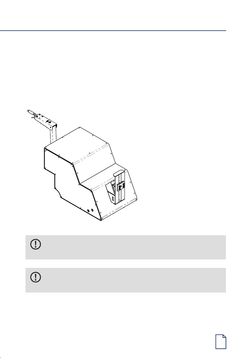
771
1940
964
REV DCN/SI
DESCRIPTION
DATE
BY
CHD
APPD
3
-
GA
01/05/17
AD
LO
FQ
TOLERANCE REQUIREMENTS
Natural
Material <not specified>
Assembled
COLOUR
PROCESS
TREATMENT
FINISH
TOUGH TUG 10T GENERAL ARRANGEMENT
Dimensions in
milimeters unless
specified.
2A Ayton Street, North Sunshine, VIC 3020
Phone: (+61) 03 9300 8500 Fax: (+61) 03 9312 3441
Unless Otherwise Stated Are:
No Decimal Place = +/- 0.5
One Decimal Place = +/- 0.1
Two Decimal Places = +/- 0.05
TOLERANCES MUST NOT BE
CUMULATIVE UNLESS
OTHERWISE SPECIFIED.
Kg
LOCATION
DO NOT SCALE FROM DRAWING
REMOVE ALL BURRS & SHARP EDGES
DIMENSIONS MARKED WITH
ARE SIGNIFICANT INSPECTION DIMENSIONS.
MASS
1:20 1/1
MATERIAL
SCALE:
Part Number
PAGE:
SIZE:
A3
Rev
©
Monday, 1 May 2017
- This dimensioned drawing is the property of Electrodrive Pty Ltd. It is supplied only to aid the making of parts for Electrodrive, and must not be used against their
interests, supplied to 3rd parties, be copied, reproduced, used for manufacture or for any other purpose without the prior written permission of Electrodrive Pty. Ltd.
3
Description
TT10-R3-DUMMY
TUGTOUGH10TNH

10
Unhitching
Always make sure the trolley is on a at level surface and apply the castor brakes
(if tted) or chock the trolley wheels.
1. Unhook the hitch via the release handle.
2. Carefully drive the Tug forward away from the trolley.
Steering
The tiller arm provides easy steering. The Tug with an attached trolley can be
manoeuvred through relatively tight areas.
It is STRONGLY RECOMMENDED that the operator lead the Tug and
trolley, rather than using the Tug to “push” the trolley.
This will ensure that the operator has a safe unobstructed view ahead. This
will also make the Tug and trolley easy to manoeuvre.
Charging
Ensure regular recharging of batteries (charging overnight after a day’s usage is
recommended). Irregular charging may cause the batteries to prematurely fail.
Leaving a machine in storage without charge for periods greater than a month can also
lead to premature battery failure. This is not covered under warranty.
For detailed charging procedures refer to Appendix 2. Misuse of the battery will void
warranty.
Only use the battery charger supplied with this Tug.
The automatic features of the supplied charger ensures that the sealed gel
batteries are not overcharged, and only a minimum amount of gas, if any at
all, are expelled during charging.
Tabla de contenidos
Otros manuales de Jacobo de ELECTRODRIVE


