Elecro Engineering G2 Instrucciones de instalación

G2 Heat Exchanger
Installation & Operating Manual

ENGLISH
www.elecro.co.uk
Contents
Page
ENGLISH ........................................................................................................ 1 - 13
ESPAÑOL ....................................................................................................... 14 - 27
FRANÇAIS ..................................................................................................... 28 - 41
DEUTSCH ...................................................................................................... 42 - 55
PORTUGUÊS ................................................................................................. 56 - 69
ITALIANO ....................................................................................................... 70 - 83
SVENSKA ....................................................................................................... 84 - 97
Русский ....................................................................................................... 98 - 110

ENGLISH
1
www.elecro.co.uk
Important Notes!
Congratulations on purchasing your new Elecro Heat Exchanger. Elecro
heat exchangers are manufactured in the UK, to exacting standards and
use the highest quality materials, to ensure exceptional performance and
reliability please take a moment to read these instructions. Your new heat
exchanger must be installed and operated as specied.
This heat exchanger must be installed correctly by qualied
personnel only, and in accordance with any national/ regional
requirements / regulations.
Product Overview
Standard G2 Heat Exchanger
Fig 1.
Nipple
End Cap
Coupling
Primary Coupling
Outer Tank
Blanking Cap
Nipple
Thermostat
pocket cap
1.5”/50mm Union
Expansion Springs
DO NOT ADJUST!

ENGLISH
www.elecro.co.uk
2
Specication
With optional Equipped kit
Transfer values
ΔT = Temperature dierence between Primary (Hot) and Secondary (Pool)
To calculate BTU multiply kW x 3412
kW x 3412 = BTU Output
Note: Maximum primary operating temperature is 95ºC
Primary booster
pump Digital / Analogue
control assembly
One way
valve
Flow
switch
1.5”/50mm Union
Thermostat
pocket cap
Expansion Springs
DO NOT ADJUST!
Standard
Power
Output
Primary
(HOT) Flow
(m³/h)
Primary
(HOT) Head
Loss (kpa)
Secondary
(POOL) Flow
(m³/h)
Secondary
(POOL) Head
Loss (kpa)
ΔT 15ºC (kW)
ΔT 20ºC (kW)
ΔT 30ºC (kW)
ΔT 40ºC (kW)
ΔT 50ºC (kW)
ΔT 60ºC (kW)
ΔT 70ºC (kW)
30-kW 1.1 6.1 10 5.0 9 11 16 20 26 30 33
30-kW 1.3 6.8 10 5.0 10 13 18 23 31 34 39
30-kW 1.3 6.8 14 7.0 11 15 20 26 34 41 46
49-kW 1.6 7.7 16 9.2 13 18 25 34 41 50 56
49-kW 1.8 8.3 16 9.2 14 20 28 38 45 55 62
49-kW 2.2 9.6 17 9.8 16 22 33 44 52 64 73
85-kW 2.4 11.3 17 10.6 22 28 40 53 64 75 81
85-kW 2.7 12.9 17 10.6 26 32 46 60 73 82 89
85-kW 3.2 14.7 17 10.6 28 34 49 64 77 90 102
122-kW 3.8 18.3 19 12.6 33 43 68 75 93 108 120
122-kW 4.2 20.0 19 12.6 36 48 70 89 108 126 143
122-kW 4.6 21.1 19 12.6 38 52 73 95 116 137 156

ENGLISH
Dimensions (mm) - Optional equipped kit
Dimensions (mm) - Standard G2 heat exchanger
Installation
Your Elecro Heat Exchanger can be installed either horizontally or
vertically. (Please see gures 4 / 5 ) A wall bracket is supplied for the
Horizontal installation only, see gure 6.
3
www.elecro.co.uk
L3
L2 (without unions)
L1
278
210
L1 L2 L3
30-kW 540 426 247
49-kW 710 596 417
85-kW 840 726 547
122-kW 1000 886 707
Fig 2.
Fig 3.
L3
L1
L2 (without unions)
131

www.elecro.co.uk
4
ENGLISH
With optional Equipped kit
Horizontal installation
POOL
POOL
PUMP
PUMP
PUMP
FILTER
FILTER
BOILER
BOILER
ELECRO HEAT
EXCHANGER
ELECRO HEAT
EXCHANGER
NON RETURN
VALVE
NON RETURN
VALVE
WATER
TREATMENT
WATER
TREATMENT
Fig 4.
Fig 5.

5
www.elecro.co.uk
ENGLISH
Horizontal wall mounting:
Your Elecro Heat Exchanger should be connected to the two
independent water circuits as follows:
1. Connection to Water Filtration Circuit (Secondary)
The heat exchanger should be plumbed inline, after the ltration pump
and lter and before any water treatment equipment. It should be fed
with clean water. Weed / debris should not be allowed to enter the heat
exchanger. Universal 1.5” / 50mm ABS plastic adapter unions for connec-
tion to rigid PVC or ABS pipe are included (stepped internal diameter to
accommodate both sizes). The heat exchanger should be installed as close
as possible to the boiler to minimise heat loss.
To assist with correct air purging and to ensure that the heat exchanger
remains full of water during operation, it should be installed at the lowest
point in the ltration circuit.
If the heat exchanger is installed in a vertical plain, it is essential that
the pool/pond water (secondary circuit) enters low and exits high.
Fig 6.
1. Fix the supplied wall bracket
as shown securing with
two screws (xings not supplied)
2. Hang the Heat Exchanger unit onto the bracket
NOTE: Wall bracket not suitable for Vertical
mounting
Wall bracket

www.elecro.co.uk
6
ENGLISH
2. Connection to Heating or Cooling Circuit (Primary)
The heat exchanger should be connected directly to the primary heating
circuit i.e. boiler, via the provided 1” BSP male brass connectors, see
diagram below.
NOTE: The circulation pump of the primary circuit should be
controlled by a thermostat, which should be connected via the
ltration pump to allow heating only when the ltration pump is
running.
Air bleed valves should be installed at the high points of the primary
circuit. To ensure correct temperature detection, it is essential that
the thermostat / thermistor is positioned at the water inlet of the heat
exchanger. The thermostat pocket and ow switch use a common port,
and can thus be swapped as required.
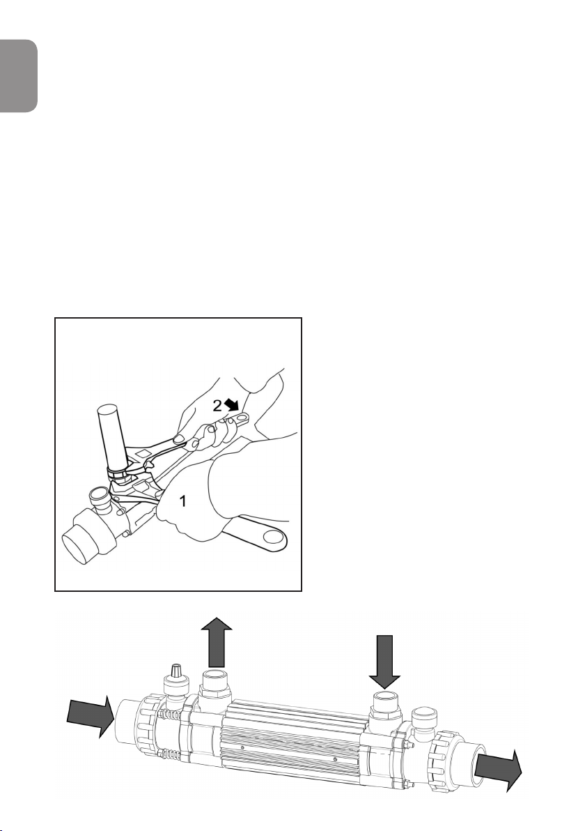
Use two wrenches to fasten ttings.
Wrench No. 1 should remain steady. NOTE: The Thermostat Control is
only included with the ’Optional’
fully equipped kit. The standard
unit is supplied only with a
Thermostat pocket and blanking
cap.
Care should be taken not to over
tighten any connections, as this
could result in damage to the heat
exchanger. Only use the supplied
brass connectors as other uncertied
connectors may leak or cause
damage to the unit.
Fig 7.
Fig 8.

7
www.elecro.co.uk
ENGLISH
Circulation direction:
The primary and secondary circuits should be installed so water ows are
counter current i.e. The hot water from the primary circuit should ow in
the opposite direction to the water in the secondary circuit.
CAUTION
If the heat exchanger is not used during winter months it must be drained
to prevent frost damage.
NOTE: For Winterising / maintenance - it is recommended that the heat
exchanger is installed with isolation valves on both water input and out-
put sides of the primary and secondary circuits. This will allow the water to
be shut o on both sides and aid removal from the system, when
required.
Water quality
To prevent damage to your heat exchanger, the water quality must be kept
within the following limits:
Chlorine Content: Max 3mg/l (ppm)
Chloride Content: Max 150mg/l
PH: 6.8-8.0
Calcium Hardness: 200-1000mg/l (ppm)
Stainless Steel heater exchangers are NOT suitable for use with salt
Water.
Equipped Heat Exchanger
(optional equipped kit)
For Elecro heat exchangers purchased with the optional equipped kit,
these include the following items:
Primary Booster Pump (Primary heating circuit)
Flow Switch
Digital or analogue temperature control
If installing with the equipped kit it is essential to take note of the
ow direction indicated on the, non-return valve and
primary booster pump.

www.elecro.co.uk
8
ENGLISH
The heat exchanger should be set up as per the following diagrams,
taking care to respect the indicated ow directions. For pool / pond water
entering on the left side of the heat exchanger, the primary water ow and
equipment should be arranged as shown in g.9.
For pool / pond water entering on the right side of the heat exchanger, the
primary water ow and equipment should be arranged as shown in g.10.
Secondary Water ow - left to right
Pump
One way valve
Thermostat
1” femal nipple
Flowswitch
Fig 9.
Otros manuales para G2
2
Tabla de contenidos
Idiomas:
Otros manuales de Equipos industriales de Elecro Engineering