Ele 600 series Manual de usuario

600 Series definition
User Manual of 600 series Radio Remote Control
Contents
Introduction
Safety Instruction
Definition of model and function introduction
Introduction for the transmitter
Introduction for the reciever
Configuration and instruction
The drawing and instruction of the transmiiter `s Configuraton
Receiver configuration
Wiring diagram
600S,600A
610S,610A
01
02
04
04
04
08
09
09
09
10
10
10
By Alex, Version:201012, China Faryuan, www.ele-b2b.com

620S,620A
System configuration
How to set the jumper
How to set the transmitting frequency
How to set ID codes
Frequency and ID codes cross-references
Installation Instruction
Installation notice
Fasten the receiver
System test
Using Notice
Troubleshooting tips
System parameter
10
11
11
12
12
14
16
16
17
18
20
22
24

communication field, Faryuan keep on develop and make technology first, try to be a
◆ The typical character of 600 series wireless remote control system
The major features of radio 600 series are as follow
The design of 600 series wireless remote control system, is based on the
600 series wireless remote control system,which is easily used, can be
01
RADIO
Introduction
alone applied in different working condition and industry equipment system, such
as automatic controlling. It can ensure safety requirement of modern industry.
Through many years professional knowledge and technical experience on Industry
leader of wireless remote control field.
maximal safeguard for the user ,and can pass kinds of interfere test of complex
condition .
CE Registration No.: VT09047176
◆ The system uses advanced microprocessors with highly evolved software
that has redundant error checking and correcting capabilities to ensure 100%
error-free transmission, decoding, and control of all output relays.
includes system parts self-diagnosing function.the transmitter has
communication check function and know the situation between transmitter and
receiver( for the detailed , see the manual)
●

It can bring good effect with correct installtion and use 600 series wireless
600 series wireless remote control system are relatively simple to use,
◆ 600 series wireless remote control system, no matter transmitter or
02
01
Safety Instruction
however, please read manual before installation,and operate with correct procedure.
remote control system.
Receiver can be matched according to sepical operation.(for the detailed , see
the manual)
◆ With more than 250 noninterference and different RF channel,it can
guarantee many machines be operated at the same time in the same area.
◆ The Degrees of protection of receiver and transmitter can be above IP65
with good configuration.The transmitter can be used outside completely against
the water come in, as the degrees of protection of water-proof and dust-proof
can be reached IP-66.The receiver is ensure to be used in bad environment as
IP65.
◆ The life of batteries can be used more with lower transmit power.Use 2
pcs“AA” batteries in the trasmitter to make sure at least transmit 100 hours in
the smallest distance.

03
◆ Check the transmitter casing and pushbuttons daily.Should any damage be
found,the unit should be removed from service.
◆ The transmitter voltage should be checked.If the voltage is low(red status
light blinking or completely off),the batteries should be replaced. If the
transmitter is not used for a long time, please take out the batteries and keep it
safe。
◆ The red emergercy stop button should be checked daily to ensure it is in
proper working .If any question, the receiver should be prohitted to use.
◆ Turn the power switch “off” after each use to avoid the mis-operation.
◆ Before starting, please confirm whether the red emergency stop button(EMS)
is turned on.
◆ Do not use the same RF channel and ID code as any other system in use at
the same facility or test at same area.
◆ Never operate a crane or equipment with two transmitters at the same time
with the same RF channel and ID code.
●The points should be followed when using

600S: 6X one speed buttons
★ Definition for 600 series
04
03
Definition of model and function introduction
6* * *
Affixal function
The sort of model
Serial number of design
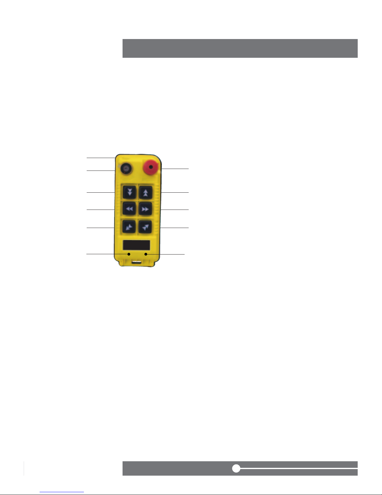
① Shell
② Power switch
③ EMS button
④ Down
⑤ Up
⑥ West
⑦ East
⑧ South
⑨ North
●
★ Introduction for functions of transmitter
①
②③
⑤
⑦
⑨
④
⑥
⑧

610S: 2 two-speed buttons+4 one-speed busttons
600A: 6X one-speed buttons+1
05
① Shell
② Power switch
③ EMS button
④ Down
⑤ Up
⑥ West
⑦ East
⑧ South
⑨ North AB AUX ,
Auxiliary Micro-button
A1: AUX Switchover button
A2: Interlock button
●
switchover buttons+1 interlock button
①
②③
⑤
⑦
⑨
④
⑥
⑧
A1 A2
① Shell
② Power switch
③ EMS button
④ Down
⑤ Up
⑥ West
⑦ East
⑧ South
⑨ North
●
◆ Attached drawing and instruction
①
②③
⑤
⑦
⑨
④
⑥
⑧

620S:6 two-speed buttons
610A: 2 two-speed buttons + 4 one-speed buttons
06
05
① Shell
② Power switch
③ EMS button
④ Down
⑤ Up
⑥ West
⑦ East
⑧ South
⑨ North AB AUX ,
Auxiliary Micro-button
A1: AUX Switchover button
A2: Interlock button
●
+1AUX switchover button+1interlock button
◆ Attached drawing and instruction
①
②③
⑤
⑦
⑨
④
⑥
⑧
A1 A2
① Shell
② Power switch
③ EMS button
④ Down
⑤ Up
⑥ West
⑦ East
⑧ South
⑨ North
●
◆ Attached drawing and instruction
①
②③
⑤
⑦
⑨
④
⑥
⑧
620A:6 directions, two speed buttons+1
07
① Shell
② Power switch
③ EMS button
④ Down
⑤ Up
⑥ West
⑦ East
⑧ South
⑨ North AB AUX ,
Auxiliary Micro-button
A1: AUX Switchover button
A2: Interlock button
◆ AUX`s funtion: Turn on the power switch, A systems are under control.
The transmitter will control B system if you press AUX button one time. The
transmitter can control two systems at the same time if you press AUX two
times.
Three times , A system will be under control. The same functions as front
intruction.
◆ BK function: BK button can control one relay independently . You can set its
funtion according to your situation.
●
AUX switchover buttons+1 interlock button
◆ Attached drawing and instruction
①
②③
⑤
⑦
⑨
④
⑥
⑧
WECAN 600
series
A1 A2

08
07
① LED Indicator light ② Nameplate ③ Cable
④ The terminal of the controlbox
⑤ Fastness screws1 ⑥ Fastness screws2
⑦ Anti-vibration spring ⑧ Installation screw
Front Back
★ Introduction for the reciever
⑤
⑥
⑦
⑧
①
③
②
④
Este manual sirve para los siguientes modelos
2
Tabla de contenidos


