Efka euramot AB60D1472 Manual de usuario

CONTROL AB60D1472
euram ot
Steuerung C ontrol C ontrôle
AB60D....
M
Typ
KL2279a
LIST OF PARAMETERS
CONNECTION DIAGRAM
TIMING DIAGRAMS
No. 402290 English
FRANKL & KIRCHNER EFKA OF AMERICA INC. EFKA ELECTRONIC MOTORS
GMBH & CO KG SINGAPORE PTE. LTD.

EFKA AB60D14723
CONTENTS Page
1 Table of Adapter Cords 5
2 Putting into Service 6
3 Operating Elements and Connectors 7
3.1 Position of the Operating Elements, Displays and Connectors 7
3.2 Connection Diagram 8
4 Connection Scheme of an SM210A Stepping Motor Control 12
4.1 Adapter Cords 13
5 Timing Diagrams 26
6 List of Parameters 58
6.1 Preset Values Depending on Mode 58
6.2 Operator Level 60
6.3 Technician Level 61
6.4 Supplier Level 65
7 Error Displays 69

EFKA AB60D14725
1 Table of Adapter Cords
Setting the functional sequence using parameter 290
Mode Designation Adapter Outputs Inputs
Power transistors
FL M1 M2 M3 ML in1 in3 in4
ST2/35 ST2/37 ST2/28 ST2/27 ST2/32 ST2/7 ST2/6 ST2/8
0 Lockstitch; e. g.
Brother (737-113, 737-913) 1112814 FL FA1 + FA2 FW - - NHT -
Aisin (AD3XX, AD158, 3310; EK1) 1112815 FL FA1 + FA2 FW - - NHT -
Pfaff (563, 953, 1050, 1180) 1112841 FL FA1 FA2 FW ML - - FLEX
Dürkopp Adler (210, 270) 1112845 FL FA1 + FA2 FW - - NHT EST
1 Lockstitch; e. g. Singer (591, 211U, 212U) 1112824 FL - FA2 FW - NHT - -
2 Lockstitch; e. g. Singer (212 UTT) 1112824 FL - FA FSPL - NHT - -
3 Lockstitch; e. g. Dürkopp Adler (467) FL FA FSPL FW ML NHT - -
4 Chainstitch;
Union Special
(34000 and 36200 replacement for US80A) 1112865 FL - FA-V FW ML LSP LSP ENTK
(CS100 and FS100) 1112905 FL - FA-V FW ML LSP LSP -
5 Chainstitch; parallel sequence
Yamato (VC series) 1112818 FL FA - FW - LSP - -
Yamato (VG series) 1113178 FL FA - FW - LSP - -
Kansai (RX 9803) 1113130 FL FA - FW ML LSP - -
Pegasus (W500/UT) 1112821 FL FA FA FW - LSP - -
Brother (FD3-B257) 1112822 FL FA FA FW - LSP ENTK -
Global (CB2803-56) 1112866 FL - - FA - LSP - -
Rimoldi (F27) 1113096 FL FW FAO FAU ML - - -
6 Chainstitch; tape cutter/fast scissors FL M1 AH1 AH2 ML - - -
7 Overlock FL M1 M2 AH ML - - -
8 Backlatch;
Pegasus 1113234 - PD≤-1 PD≥1 - - LSP N.AUTO -
9 Backlatch;Yamato (ABT3) 1112826 - PD≤-1 PD≥1 - - LSP N.AUTO -
Backlatch;Yamato (ABT13, ABT17) 1113205 - PD≤-1 PD≥1 - - LSP N12.AU N9.AU
10 Lockstitch; e. g. Union Special 1113199 FL - FA-V FW ML - - -
(63900AMZ replacement for US80A)
11 Reversal of motor rotation with pedal in pos.–2 FL DR-UK PD=-2 ML ML N.POS - -
12 Reversal of motor rotation with input in3 FL DR-UK PD=0 ML ML N.POS DR-UK -
13 Lockstitch; Pfaff (1425) 1113072 FL FA FSPL FW ML NH POS2 DB
14 Lockstitch; e. g.
Juki (5550-6) 1112816 FL FA1+2 - FW - - - -
Juki (5550-7) 1113132 FL FA1+2 FZ FW - - - -
17 Chainstitch; Pegasus FL M1 M2 M3 ML - - -
18 Overlock; Bottoms FL M1 AH M3 ML - - -
19 Lockstitch; Macofrey FL FA-R FA-V FW ML - - -
20 Lockstitch; Juki (LU1510-7) 1113200 FL FA FSPL - - - BIT0 BIT1
22 Lockstitch; Brother (B-891) FL FA FSPL FW ML - - -
ATTENTION!
Before switching functional sequences, detach cables from the inputs and outputs! Please ensure that the
machine installed provides the functional sequence to be set! Then proceed with the setting using
parameter 290!

EFKA AB60D1472 6
Explanation of letter symbols of the previous page and chapter ”Timing Diagrams“
Outputs: Inputs:
FL = Sewing foot lifting NHT = Needle up/down
FA1 = Thread trimmer pos. 1...1A EST = Single stitch
FA2 = Thread trimmer pos. 1A...2 FLEX = External sewing foot lifting
FA1+2 = Thread trimmer pos. 1...2 N.POS = Positioning speed
FSPL = Thread tension release N.AUTO = Automatic speed
FA-R/FA-V = Thread trimmer backward/forward N9.AU = Automatic speed n9
ML = Machine running N12.AU = Automatic speed n12
FW = Thread wiper LSP = Machine run blockage
AH/AH1/AH2 = Tape cutter / Tape cutter 1/ Tape cutter 2 DR-UK = Reversal of motor rotation
DR-UK = Reversal of motor rotation NH = Needle up
PD=0 = Pedal step 0 POS2 = Run to position 2
PD-2 = Pedal step -2 DB = Speed limitation n12
FAO = Needle thread trimmer ENTK = Unlocking the chain
FAU = Bobbin thread trimmer BIT0 = Speed limitation bit 0
FZ = Thread puller BIT1 = Speed limitation bit 1
PD≥1 = Pedal steps 1...12
PD≤-1 = Pedal steps –1 / -2
2 Putting into Service
Before putting the control into service, the following must be ensured, checked and/or adjusted:
The correct installation of the drive, position transmitter and accompanying devices, if necessary
The correct selection of the trimming operation using parameter 290
If necessary, the correct adjustment of the direction of motor rotation using parameter 161
The correct selection of functions of the keys (inputs) using parameters 240...249
The correct positioning speed using parameter 110
The correct maximum speed compatible with the sewing machine using parameter 111
The setting of the positions
The setting of the remaining relevant parameters
Start sewing in order to save the set values
See instruction manual for details!

EFKA AB60D14727
3 Operating Elements and Connectors
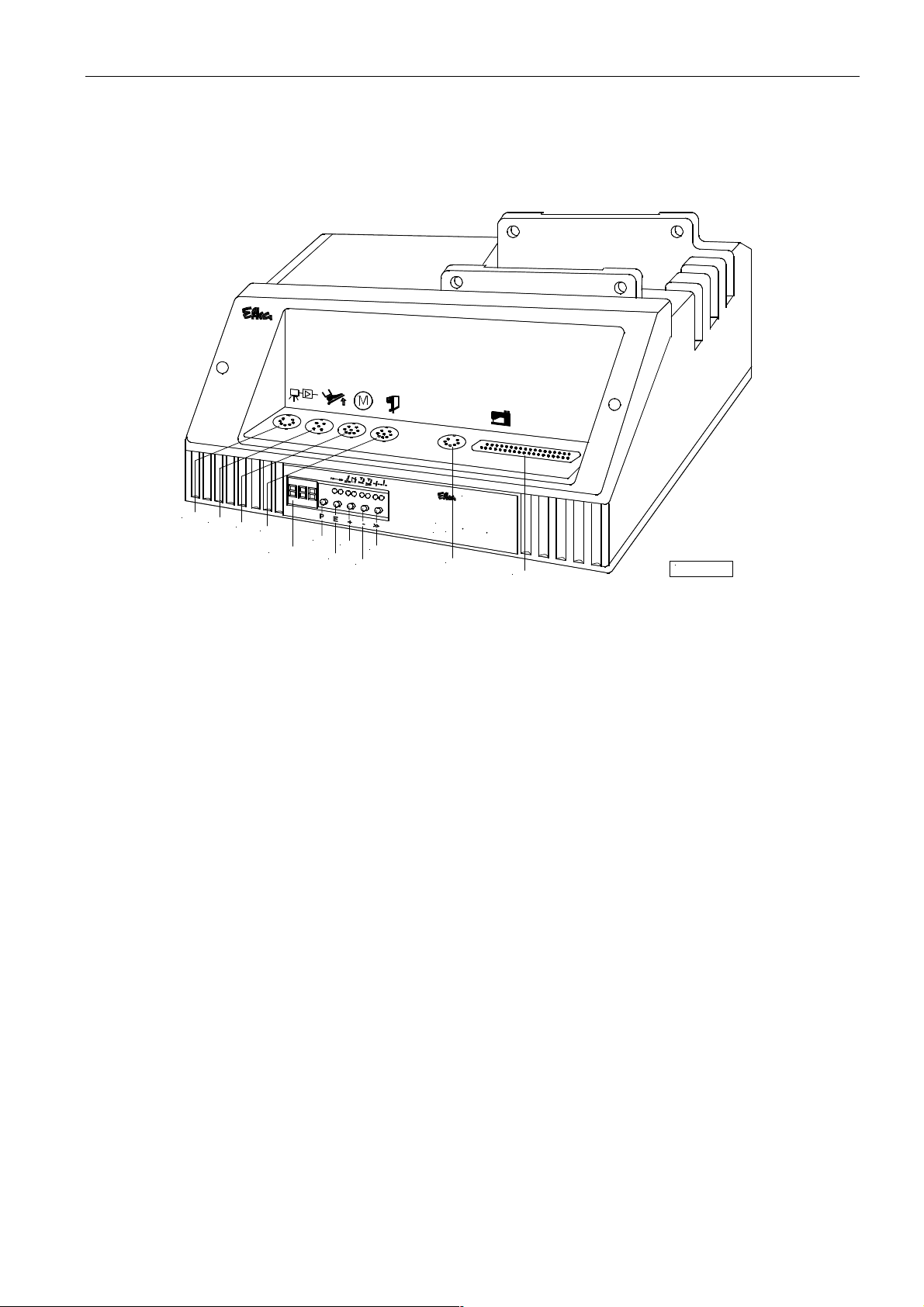
3.1 Position of the Operating Elements, Displays and Connectors
Steueru ng C ontrol C o n trô le
euram ot
AB60D....
B4
Typ
ST2
Display
B1
B80 B2
B18
S5
S1
S4
S2
S3
M
KL2280a
S1 P key Call or exit programming mode
S2 E key Softstart on / off
Enter key for modifications in the programming mode
S3 + key Thread trimmer/thread wiper on / off
Increase of the value indicated in the programming mode
S4 – key Automatic sewing foot lift at stop in the seam On/Off
Automatic sewing foot lift after trimming On/Off
Decrease of the value indicated in the programming mode
S5 >> key Basic position 1 or 2
Shift key in the programming mode
Display 3 digits
B1 Connection of position transmitter
B2 Connection of commutation transmitter for d.c. motor
B4 Inputs of keys or switches
B18 Connection of light barrier module or stepping motor control
B80 Connection of actuator
ST2 Inputs and outputs for solenoids, solenoid valves, displays, keys or switches

EFKA AB60D1472 8
3.2 Connection Diagram
Inputs switched to 0V
in1 - Input 1 M1 - Output 1 POS1 - Position 1
in3 - Input 3 M2 - Output 2 POS2 - Position 2
in4 - Input 4 M3 - Output 3 GEN - Generator impulses
R-N-EXT - External potentiometer FL - Sewing foot lifting
for speed limitation ML - Machine running
(50kΩ)
ATTENTION!
When connecting the outputs, ensure that a total power of 70VA constant load will not
be exceeded!

EFKA AB60D14729
Inputs switched to +24V
1) Nominal voltage 24V, no-load voltage max. 36V
2) Transistor output with open collector max. 40V, 10mA
3) Nominal voltage 15V, Imax = 30mA
4) Nominal voltage 5V, Imax = 20mA
*) Front view of the socket (component side) and/or rear view of the plug (soldering side)
ATTENTION!
When connecting the outputs, ensure that a total power of 70VA constant load will not
be exceeded!

EFKA AB60D1472 10
Inputs switched to 0V Inputs switched to +24V
in1 - Input 1
in3 - Input 3
in4 - Input 4
Functions of the keys can be selected for all inputs in1, in3 and in4 of the sockets ST2 and B4 using parameters 240, 242
and 243.
LSM001A - Reflection light barrier module
* - Parameter 239 = 0 The light barrier function has been selected.
(Identified when switched to 0V)
** - Parameter 239 = 1...44 Various input functions are possible on socket
B18/5
+5V = Connect pins1 and 2 on the right with jumper (factory setting)
+15V = Connect pins 3 and 4 on the left with jumper
J1
KL2345
3
4
1 3
+5V
J1
2 4
1
+15V
J1
2
1) Nominal voltage +24V, no-load voltage max. 36V
2) Nominal voltage +5V, 100mA (repluggable to +15V, 100mA)

EFKA AB60D147211
Table: Coding of the Pedal Steps
Pedal step D C B A
-2 H H L L Full heelback (e. g. initiating the seam end)
-1 H H H L Slight heelback (e. g. sewing foot lifting)
0 H H H H Pedal in pos. 0 (neutral)
½ H H L H Pedal slightly forward (e. g. sewing foot lowering)
1 H L L H Speed stage 1 (n1)
2 H L L L Speed stage 2
3 H L H L Speed stage 3
4 H L H H Speed stage 4
5 L L H H Speed stage 5
6 L L H L Speed stage 6
7 L L L L Speed stage 7
8 L L L H Speed stage 8
9 L H L H Speed stage 9
10 L H L L Speed stage 10
11 L H H L Speed stage 11
12 L H H H Speed stage 12 (n2) Pedal fully forward
EB.. Actuator

EFKA AB60D1472 12
4 Connection Scheme of an SM210A Stepping Motor Control
V810
/
V820
variocontrol 810
321
M
4
E
+
P
1
1
-
4
SM 01
8
variocontrol 820
321 4
7654321 9
65
11 1210
P E
ST1
ST1
B19
L S M ...
B776
B5
..V8
B776
1
B5
mot
M
B18
B18
c o n tro l
SM210....
0 I
mot
Nr. 1113113
B19
M
Steuerung C ontrol C o n trô le
AB60D....
euram ot
Typ
AB60D....
D
C
1600
KL2510
The AB60D.... control (B18) and the SM210A....stepping motor control (B18) are connected by means of adapter cord no.
1113113.
If a light barrier is required for the sewing process, it must be connected to socket B9 on the stepping motor control. The
light barrier signal is transmitted via the connecting cable from the SM210A to the sewing drive.
Otros manuales para euramot AB60D1472
1
Tabla de contenidos
Otros manuales de Sistema de control de Efka